
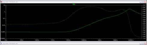
But the models can be weak up that high and the real MOSFETS behave much better in RF with more current...? For up to 1MHZ region I have seen AP results for the 1.1 PSU from Jack and they follow for sure. Actually, they had been a little better than the modeling itself. I used the same analysis method and library here.
I am getting ready to build this. In a desire to learn, may I ask a couple of questions about the LED's.
1. What process are you using to measure them for matching?
2. What is the actual function that they provide in the circuit?
3. I notice in some of the pictures of individual amps that there are two different colors of LED's in the same bunch. What is the reason for that.
Thanks, Terry
1. What process are you using to measure them for matching?
2. What is the actual function that they provide in the circuit?
3. I notice in some of the pictures of individual amps that there are two different colors of LED's in the same bunch. What is the reason for that.
Thanks, Terry
I am getting ready to build this. In a desire to learn, may I ask a couple of questions about the LED's.
1. What process are you using to measure them for matching?
2. What is the actual function that they provide in the circuit?
3. I notice in some of the pictures of individual amps that there are two different colors of LED's in the same bunch. What is the reason for that.
Thanks, Terry
- I put all LEDs in series with a 2SK170BL on a 12V PSU. Mix and match till I got 9V for 5 LEDs and 5.4V for 3 LEDs. There is a post by Salas somewhere. Just search for 'party trick' or something like that.
- Voltage reference.
- My yellow LEDs were mostly around 1.9V and my red LEDs mostly around 1.7V. This way I could get closer to the target voltage references.
I am getting ready to build this. In a desire to learn, may I ask a couple of questions about the LED's.
1. What process are you using to measure them for matching?
2. What is the actual function that they provide in the circuit?
3. I notice in some of the pictures of individual amps that there are two different colors of LED's in the same bunch. What is the reason for that.
Thanks, Terry
1. DMM that can drive an LED when in diode mode, semiconductor characterization gadget, 9V battery +1.5K resistor in series, fet ccs, etc. Any of those handier 2U.
2. Voltage references.
3. They mixed and matched Vf from different colors for a larger span to make alike totals.
But don't go in great lenghts about matching LEDS for this circuit. A reasonable match between the groups of 3 and groups of 5 Vf total is fine.
- I put all LEDs in series with a 2SK170BL on a 12V PSU. Mix and match till I got 9V for 5 LEDs and 5.4V for 3 LEDs. There is a post by Salas somewhere. Just search for 'party trick' or something like that.
- Voltage reference.
- My yellow LEDs were mostly around 1.9V and my red LEDs mostly around 1.7V. This way I could get closer to the target voltage references.
Cross posted.🙂
Thanks. I understand answers to 1 & 3 but "Voltage references" doesn't tell me enough to understand. Could you elaborate a little? I have built several amps and not of them use LED's in the circuit.
Thanks, Terry
Thanks, Terry
LEDS are one of the many ways to utilize a voltage reference. Arguably one of the most easy to get and noiseless. In our circuit they consist a steady voltage to produce the main CCS current against it, plus they build up the output voltage setting value.
Thanks for trying. Probably just to advanced for me at this point. Thought I would try.
Thanks, Terry
Thanks, Terry
Its not that perplexing. Follow me. I needed a constant current source using a MOSFET so to current limit and kinda isolate the PSU. The MOSFET has one internal value that is steady enough at any given current bias point. That is VGS. A voltage that develops between its gate and source pins. If I could find another steady voltage to pitch against it then I could set a steady current based on their voltage difference via a resistor. I built that other Vref by using 3 LEDS.
Then in the parallel or "shunt" PSU part I needed a Vref to set a +/-10V value and to pitch the output fluctuations caused by the audio circuit load against it. I built it by 5 LEDS. A gain loop in the form of a transistor compares the output to the 5 LEDS reference and corrects it by telling the output MOSFET to add or subtract a bit of current. Mini JFET constant current sources at the tails of all those LED strings stabilize them further.
Then in the parallel or "shunt" PSU part I needed a Vref to set a +/-10V value and to pitch the output fluctuations caused by the audio circuit load against it. I built it by 5 LEDS. A gain loop in the form of a transistor compares the output to the 5 LEDS reference and corrects it by telling the output MOSFET to add or subtract a bit of current. Mini JFET constant current sources at the tails of all those LED strings stabilize them further.
Thanks, I think I understand now. So this makes me question how this is done without using LED's because I have not seen it before in the amps I have built and surely they must need to do the same thing.
I received the transformer from Antek today. I just did a quick check and it is putting out 12.8Vac unloaded.
So now my uneducated mind is asking, if the circuit we were just talking about drops the voltage to +/- 10V, why would it matter if the transformer is 12V or 15V? What am I missing?
Thanks
I received the transformer from Antek today. I just did a quick check and it is putting out 12.8Vac unloaded.
So now my uneducated mind is asking, if the circuit we were just talking about drops the voltage to +/- 10V, why would it matter if the transformer is 12V or 15V? What am I missing?
Thanks
When voltage references are used (their presence is not ubiquitous in audio, rather much more in instrumentation) they can be just diodes, zeners, special 3 legged chips, vbe, vbe multipliers, many things. LEDS are not that much common. But I have seen them in power amps too. Here is a picture of some SMT ones glowing underside a class A amp I use for instance: TSSA with Cmultiplier PSU filter
12.8VAC is going to be OK.
Its main constant current source needs some adequate voltage drop from input to output DC to function stably enough. 15V is just more security against low mains situations.
12.8VAC is going to be OK.
Its main constant current source needs some adequate voltage drop from input to output DC to function stably enough. 15V is just more security against low mains situations.
10.67v and 10.13v
Those are my numbers. My first build completed!!! Thanks everyone!! I thought maybe my house was going to blow up when I first plugged it in 😀
Those are my numbers. My first build completed!!! Thanks everyone!! I thought maybe my house was going to blow up when I first plugged it in 😀
Hi Guys,
I received all my parts today. I've got just about everything soldered in but I am at the LED point. I just tested all of them using a 9V supply and a 1K resistor. They read between 1.901V to 1.915V. Most of them are between 1.901 and 1.906. Maybe 5 of them between 1.910 and 1.915. What exactly am I looking for and how would you match these in the circuits.
Thanks, Terry
Hi Guys,
I received all my parts today. I've got just about everything soldered in but I am at the LED point. I just tested all of them using a 9V supply and a 1K resistor. They read between 1.901V to 1.915V. Most of them are between 1.901 and 1.906. Maybe 5 of them between 1.910 and 1.915. What exactly am I looking for and how would you match these in the circuits.
Thanks, Terry
You want to have 2 matching sets of 5 LEDs total voltage and 2 matching sets of 3 LEDs total voltage.
Since you are on the low side of the transformer voltage, it would be helpful to hit the target of 9v and 5.4v. You would have to buy some LEDs like these: HLMP-K150 Avago Technologies | Mouser
They are 1.6 volt red LEDs and with a pair of these and 3 of yours you could get close to the 9v (19.1+1.91+1.91+1.6+1.6=8.93) and the same for 5.4v (19.1+1.91+1.6=5.42).
Salas can tell you how critical these voltages are but I think there is some wiggle room.
Rush
Shoot, I just remembered that I had to order the 2SK170's from a guy on ebay. I guess I don't have all my parts. Looks like I need some more LED's too. Oh well, Another project undone sitting on the shelf. At least it will have company. 😀
You want to have 2 matching sets of 5 LEDs total voltage and 2 matching sets of 3 LEDs total voltage.
Since you are on the low side of the transformer voltage, it would be helpful to hit the target of 9v and 5.4v. You would have to buy some LEDs like these:
They are 1.6 volt red LEDs and with a pair of these and 3 of yours you could get close to the 9v (19.1+1.91+1.91+1.6+1.6=8.93) and the same for 5.4v (19.1+1.91+1.6=5.42).
Salas can tell you how critical these voltages are but I think there is some wiggle room.
Rush
Buy this LED instead: HLMP-Q150 Avago Technologies | Mouser
It has more current that will match your other LEDs. Of course there will be some voltage variances with these as well.
Rush
I wish I had seen this earlier. I ordered mine from am guy in Israel. Who know when I will get them of if they are fake. This is probably a dumb question but it appears that those Jfets are maybe being fazed out. What is it about them that makes them so much better than BJT? I have tons of BJT devices and they are readily available. Can't these circuits be tweaked to work just as well with those?
Thanks, Terry
Thanks, Terry
- Home
- Amplifiers
- Pass Labs
- Mezmerize DCB1 Building Thread