Solder in a wire with a loop on the end. This gives you 3 test points that you can securely and safely hook on to.
It also mentions with red letters in the footnotes "If you decide to ride over the use of 2X12v transformer add sinks". So it actually tells you may also use higher trafo if going beyond minimum CCS with sinks anyway.
Thanks Salas.
Feeling a bit nervous to hook up. Are you aware of any pics illustrating this? I have a hammond toroidal transformer 12 x 12. Also I am really doubting my knowledge to hook up this transformer properly. Thanks.
Feeling a bit nervous to hook up. Are you aware of any pics illustrating this? I have a hammond toroidal transformer 12 x 12. Also I am really doubting my knowledge to hook up this transformer properly. Thanks.
Here is the manual for my 50va 2x12v toroid hammond transformer. THanks.
http://hammondmfg.com/pdf/182%20Insert.pdf
http://hammondmfg.com/pdf/182%20Insert.pdf
Plug your primaries according to the spec, for 117 VAC if you have that, for 234 if thats what you have.
Plug secondaries according to the Series Connection spec. Blu-Gry gets together in the middle hole marked CT.
Check for if the trafo gets warm or hums. If so, plug out asap. Measure DC voltage at test points on card..
Plug secondaries according to the Series Connection spec. Blu-Gry gets together in the middle hole marked CT.
Check for if the trafo gets warm or hums. If so, plug out asap. Measure DC voltage at test points on card..
Last edited:
Thanks Stajo.
Into the PCB: Grey&Blue into middle. Yellow into left. Red(ish) color into right.
For the primaries: for 117V: Black to negative. White and Brown to ground. Orange(ish) color to positive.
Does this seem right?? Thanks!
Into the PCB: Grey&Blue into middle. Yellow into left. Red(ish) color into right.
For the primaries: for 117V: Black to negative. White and Brown to ground. Orange(ish) color to positive.
Does this seem right?? Thanks!
I wonder if the Hot Rod boys only hear a difference because they think they can. My ears are pretty good and I couldn't hear any difference when driving the Salas above 200mA.
Thanks Stajo.
Into the PCB: Grey&Blue into middle. Yellow into left. Red(ish) color into right.
For the primaries: for 117V: Black to negative. White and Brown to ground. Orange(ish) color to positive.
Does this seem right?? Thanks!
Nope. Dont plug ground on primaries. Blk AND Brn on one, hot if you want (theres no plus/positive and minus/negative on AC) and Wht And Orn on the other. Leave ground out of the transformer. Sometimes theres a Ground connection to the core, that is usually Green/Yellow.
Last edited:
I wonder if the Hot Rod boys only hear a difference because they think they can. My ears are pretty good and I couldn't hear any difference when driving the Salas above 200mA.
They are too many already to dismiss them off hand. Still, subjective is subjective. So no worries. The only things sure are that the output impedance of the supply and its HF flatness gets better.
Does this seem right??
A friendly advice from me. Read up some on basic electricity, or ask someone with knowledge to help you with the high voltage before messing to much with things.
Google "Bulb tester" and check so you have a residual current device in your house/apartment. That can save your life.
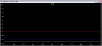
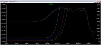
Here are a couple of LTSPICE screens I had made once about the PSU current levels and its Zo curves. Now, we can say that from 1 milliohm to 1/2 milliohm its no big deal. But another one may say, hey its double the damping factor to the load if you look at it differently. Blue line is the 200mA level. Then on it gets difficult to gain Zo. Still the HF knee progresses.
Attachments
Salas,
how does the Buffer output to the "load" vary with the change in Rs from the PSU of 0.0005ohms?
how does the Buffer output to the "load" vary with the change in Rs from the PSU of 0.0005ohms?
0.0005 from the 60mA to 200mA bias choice for instance? That one plotted tier at least all seem to report appreciating. Super rudimentary variation from the buffer to its load behavior I would suppose. Should have to do with listening to the PSU itself as it can be argued its in the signal path itself as the total current closes its loop?
Thanks for not answering my question. How about a simulation like you have for the PSU but applied to the Buffer where the parameter being investigated is the Rs to the Buffer?
Now try to convince Katie's Dad that the change of <0.0005ohms in source impedance is why he can't hear any change in sound quality once he moves from 200mA to 1500mA.
Now try to convince Katie's Dad that the change of <0.0005ohms in source impedance is why he can't hear any change in sound quality once he moves from 200mA to 1500mA.
Last edited:
I can't be answering the most intriguing SQ VS PSU question so easily. I am looking for a definite technical clue myself too. I will try such a simulation at a point.
But he can hear 60mA to 200mA? Its from 1mil to 1/2 mil again.
But he can hear 60mA to 200mA? Its from 1mil to 1/2 mil again.
Then maybe it's not the change from 0.001ohms to 0.0005ohms in the audio frequency range that is affecting the performance of the Buffer.
Look at the impedance in the frequency ranges outside audio.
There the impedances are very much higher. Small changes in the very low Rs values around the audio frequencies may not affect the audio performance of the Buffer.
I suspect it's the tens of ohms change in impedance in the 20kHz to 10MHz that might be affecting the Buffer performance. That's where RF interference attenuation may well be affecting Buffer performance.
I am suggesting it's NOT the low impedance that is giving the change, it's the interferences that are being reduced by avoiding high Rs in the RF region that may be heard.
Simulation may be able to show this if the appropriate parasitics are included in the model.
It's here that decoupling of the Buffer's supplies may show the effects that are being heard.
Since I'm not a simulator user, I can't help guide your endeavors.
- Home
- Amplifiers
- Pass Labs
- Mezmerize DCB1 Building Thread