The ones you already use are not matched at all? Just random?
P.S. Try using some tamer LEDS for the 10.61V section in the group of five so to bring it a bit nearer 10V. That should help you finally judge your now offset better.
P.S. Try using some tamer LEDS for the 10.61V section in the group of five so to bring it a bit nearer 10V. That should help you finally judge your now offset better.
matched fets
Hi,
What is the worst case scenario if none of the fets are matched? I have some sk170 which I don't think they are matched and I intend to build the mesmerize with these fets.
Thanks.
Pmchoong
Hi,
What is the worst case scenario if none of the fets are matched? I have some sk170 which I don't think they are matched and I intend to build the mesmerize with these fets.
Thanks.
Pmchoong
To have excessive DC offset that will warrant an output capacitor coupler and a bit more THD maybe. Depends on chancing to the constant current fet over driving the signal fet above it.
1) Which means if the Fets aren't matched :
1) you will get a very high DC offset and that will blow the output capacitor. Is this correct?
Or :
2) you will get a higher than normal DC offset, overwork the output capacitor (thus shortening its lifespan) and maybe the THD would be a little higher too.
But the sound quality remains the same.
Thanks.
PMChoong
To have excessive DC offset that will warrant an output capacitor coupler and a bit more THD maybe. Depends on chancing to the constant current fet over driving the signal fet above it.
This is optimally a full DC coupled buffer. If it will show enough output offset it will need be blocked with a capacitor. That is all. Capacitors are to block DC up to their rating printed on them. They are not in danger doing that, its one of their normal jobs.
The possible problem I mentioned above would appear while measuring voltages in the range of mV using the V scale in the multemeter.
Try setting the new multimeter to the mV range scale and then measure the offset again, just to be sure
Try setting the new multimeter to the mV range scale and then measure the offset again, just to be sure
Hello Salas,
I have seen on “Toshiba 2SK170BL for sales” some DIYs requesting from Spencer 8.5mA matched 2SK170, or even matched to 9mA Idss.
Is there a particular reason for this, would JFETs with higher Idss at 0Vgs have better linearity, less distortions?
One more thing to ask, if I would like to have a more safe approach and add DC blocking cap on the output, and the input resistance of my Power Amp is 20kOhms, what cap value would be OK, can you also recommend a good cap chemistry-P/Number.
At 9mA there is 90mW to dissipate for each Jfet as we use it here and better don't go higher for long term reliability, there is enough transconductance already. THD differences from say 7-9mA are not drastic.
Use 6.8uF I would say. Prices and subjective evaluations vary widely but an Obbligato MKP oiler, the one in black can with flying leads should be economical and effective since you need some uF.
Use 6.8uF I would say. Prices and subjective evaluations vary widely but an Obbligato MKP oiler, the one in black can with flying leads should be economical and effective since you need some uF.
Salas, thanks so much for your quick reply. Few more things to ask.
Also higher value, like 10uF should also work? Voltage, any voltage should work, 400V for example? Would 400V Jantzen metallized polypropylene be adequate choise? The conection point, is is OK to:
1. Connect cap between the 220 Ohm resistor (and the relay flying contact? In other words cut the trace between 220 Ohm resistor right lead on schematic (left one is connected to midle point of two JFETs) and insert it between relay. In this case the right side of the cap goes to the output through relay contact and the is connected to GND through existing 1M resistor?
2. Or to connect/insert a cap between the 1 MOhm resistor and output connector, adding another 1M resistor to the GND on connector side, the output to the power amplifier?
Just one more thought: for item (2), would this be even better to use a cap before relay. Like JFETs middle point goes to existing 220 Ohm resistor and cap in-series with it, from the right side of the cap: to 1M resistor to GND and to center (flying) relay contact, other relay contact goes to power amp input and through 1M resistor to GND (or even no this last 1M resistor at all relay contact straight to power amp?. Would this be more logical?
It will be equivalent to having the cap in series with the existing DC coupled output on the PCB. Save hacking the board. Use 2 parallel RCA outputs, one direct, the other with the 6.8uF to 10uF output capacitor, so to have both DC coupled and AC coupled outlets. Depending on what you drive (AC/DC input coupled amps or DC input coupled amp with output DC fault protection relays) it will be a flexible configuration.
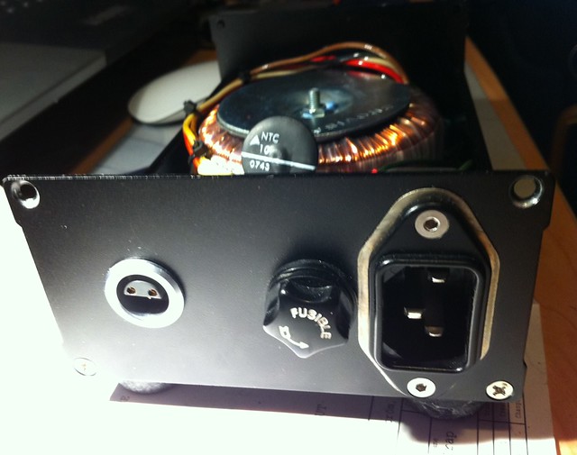
Finally I did the hot-rod first stage and I'm very impressed, the bass are incredible, as well the sound stage are wider and deeper.
I'm using two 16 Ohm resistors in parallel, the DCB1 are now close to 200m to 210mA (The voltage across the resistor drops a bit) (The DCB1 is cold).
A photos of the "near to finish" Mezmerize:
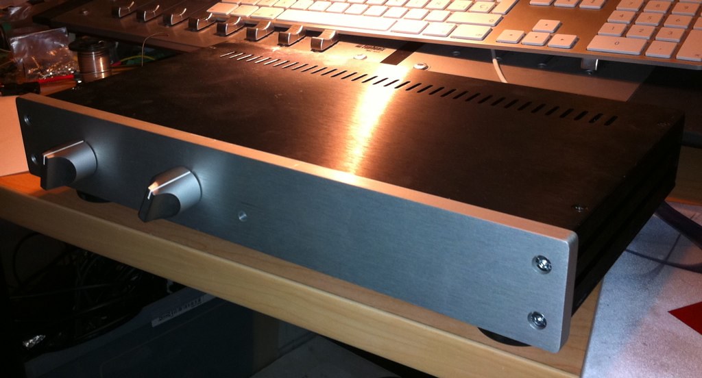
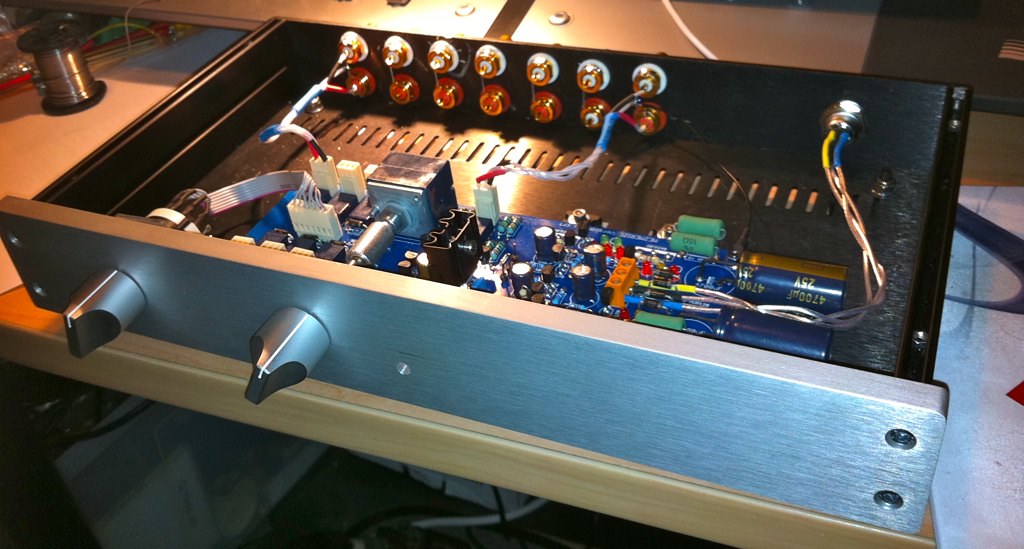
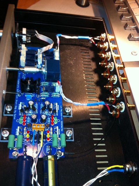
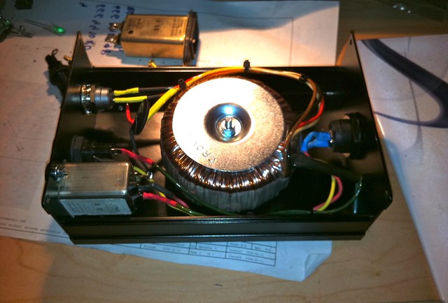
Thanks Salas!
Hi all,
I'm looking for ideas for mounting the volume and source selectors on a thick front plate (the one from the store). It looks like I'll need to mount them similar to the one above but I can't see it in the photo. Any help would be appreciated!
Mark
Mark,
Could you be more specific please?
Are you referring to the shaft extension on the volume?
Could you be more specific please?
Are you referring to the shaft extension on the volume?
It looks like the input switch is mounted on a piece of L shaped alluminium.
Extension brackets like this are available but where in the USA I don't know.
Extension kit Hifi Collective
Extension brackets like this are available but where in the USA I don't know.
Extension kit Hifi Collective
Mark,
Could you be more specific please?
Are you referring to the shaft extension on the volume?
Sorry, I'm looking for ideas for a mounting bracket, and for an extension for the alps volume pot. The source switch already has an extended shaft.
What is the wise target of Idss for matched 2SK170BL in order to get the lowest THD?
Do they have to be matched with +/- 0.05mA, or 0.1-0.15mA range would be adequate?
Just want to understand what numbers to get to Spencer ordering JFETs.
Do they have to be matched with +/- 0.05mA, or 0.1-0.15mA range would be adequate?
Just want to understand what numbers to get to Spencer ordering JFETs.
An easy, easy extension shaft for the pot is a short piece of rubber tubing (automotive, vacuum or gas line) slipped over the pot shaft with another metal shaft on the other end. You can use a grommet or plastic tube (straw) where it penetrates the faceplate so it's not metal on metal. The knob will hide the penetration grommet. Hobby shops, and hardware stores have all different sizes of metal tubing. Doesn't have to be solid. Set screws on the knob will hold just fine.
[]--==----
pot >shaft>tubing>shaft
These ascii drawings don't usually work out well, but I tried.
Ron
[]--==----
pot >shaft>tubing>shaft
These ascii drawings don't usually work out well, but I tried.
Ron
What is the wise target of Idss for matched 2SK170BL in order to get the lowest THD?
Do they have to be matched with +/- 0.05mA, or 0.1-0.15mA range would be adequate?
Just want to understand what numbers to get to Spencer ordering JFETs.
Its primarily about offset. THD here has to do with transconductance and signal level mainly. Try to get the best but 0.1mA deviation is no party stopper.
Salas, can you please clarify:
About the potentiometer-mutistep switch: what DIY-selfers use the most as a good aesthetitac approach and most nice rotation feeling, is it a Alps type 20kOhm potentiometer or DACT, GOLDPOINT Stepped Attenuator?
It is a radial type of can, both flying leads on the same side (end), not the axial type of cap?but an Obbligato MKP oiler, the one in black can with flying leads should be economical and effective since you need some uF.
About the potentiometer-mutistep switch: what DIY-selfers use the most as a good aesthetitac approach and most nice rotation feeling, is it a Alps type 20kOhm potentiometer or DACT, GOLDPOINT Stepped Attenuator?
- Home
- Amplifiers
- Pass Labs
- Mezmerize DCB1 Building Thread