…chop the sink you got a little.
… mount another nowhere connected TO-220 device back to back or top and up to augment the thermal capacity of the activated one until he finds a more elegant way? 🙂
Any TO-220. Even a broken one.
I'll chop
good morning, anyway 🙂🙂
fast measurements
Dear Salas and all
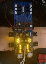
B1 seems to be quite fine.
I got the heatsinks mounted (gosh was that narrow!), B1 lit up very nicely, and I measure:
-9.81 V
9.87 V
The heatsinks are warming quite differently, though: 41°C versus 30.3°C (just above the second/centermost mosfet)
What/where else can I check before connecting pot / selector?
thank you, and have a good afternoon!
Dear Salas and all
B1 seems to be quite fine.
I got the heatsinks mounted (gosh was that narrow!), B1 lit up very nicely, and I measure:
-9.81 V
9.87 V
The heatsinks are warming quite differently, though: 41°C versus 30.3°C (just above the second/centermost mosfet)
What/where else can I check before connecting pot / selector?
thank you, and have a good afternoon!
Good morning Salas
-1.704 V on the hotter running side,
1.549 V on the cooler running side
Is that too big a diff?
Thanks
must go do work, would prefer to play with B1 🙁
Voltage drops across the 2x18 Ohm resistors per side?
-1.704 V on the hotter running side,
1.549 V on the cooler running side
Is that too big a diff?
Thanks
must go do work, would prefer to play with B1 🙁
About 18mA diff. Piggy back a 100 Ohm normal sized resistor over one of the 18Ω set resistors on the 1.55V side. It should equalize the mA result. Now bit off due to random Vgs diff between pos neg Mosfets.
About 18mA diff. Piggy back a 100 Ohm normal sized resistor over one of the 18Ω set resistors on the 1.55V side. It should equalize the mA result. Now bit off due to random Vgs diff between pos neg Mosfets.
Good morning, Salas
I found some time to continue.
With the 100r, I now have:
left side | right side
==============
(cooler) | (warmer)
9.88 V | -9.82V
172 mA | -177.7 mA
5 LED
9.27 V | -9.2 V
67.4 mA | -67.7 mA
3 LED
5.68 V | -5.64 V
9.3 mA | -10.5 mA
Voltage Drops (across the 2x18 Ohm)
1.43 V | -1.71 V
138 mA | -187 mA
Heatsink
≤40°C | ≤ 30°C
Are those values ok?
(I didn't pay great attention to where I put the red/black tip in the circuit. While measuring the mA, the diodes went off... I hope I didn't damage anything)
Now I'll start with the connections.
Thank you again
david
Wiring that thing up
I need a little assistance on how to connect the potentiometer and selector-switch. Head fuming.
Could someone please just point me to a picture (sketch, foot, schematic) of what to connect where?
I know, I know, DIY... big sorry for annoying the community with those Q, but 😕
david
I need a little assistance on how to connect the potentiometer and selector-switch. Head fuming.
Could someone please just point me to a picture (sketch, foot, schematic) of what to connect where?
I know, I know, DIY... big sorry for annoying the community with those Q, but 😕
david
I need a little assistance on how to connect the potentiometer and selector-switch. Head fuming.
Could someone please just point me to a picture (sketch, foot, schematic) of what to connect where?
I know, I know, DIY... big sorry for annoying the community with those Q, but 😕
david
There is an area between the input relays with 1,2,3,4,5,6,GND pads in a row. The switch has 6 pins on each side and one near that relates with each side's group. Wire one side's only 1-6 pins to those pads and their related one to GND pad.
Lay the PCB down on a table with its output relay pointing away from you. Lay your pot over the 15k-25k Alps frame PCB area. Its rotating shaft pointing towards you. Wire its legs one by one in order with the pot pads inside the PCB's Alps pot frame.
Salas
Thank you very very much for your patient guidance.
B1 isn‘t fully functional yet (1 channel wasn‘t connected, and right now it‘s even mute—I hope it is still a connection glitch since everything is alight and clicking [emoji4])
Off topic question:
Since you excel as a true master of these arts and have a sense for nice parts, may I ask you what connectors (PCB-wires) you would recommend for connecting the B1 ?
I‘m a bit reluctant to just solder all those wires, because I’ll (probably) do some experimenting with wires (silver), connectors (non-camac et al), attenuator etc... so I’m after a sensible but still nifty solution... many connectors disqualify themselves because the require expensive equipment.
Thank you
David
may I ask you what connectors (PCB-wires) you would recommend for connecting the B1 ?
Thank you
David
Mogami low capacitance shielded coax wire various thickness types, Neutrik or Amphenol connectors, Sn62 solder alloy, Blue Jeans Cable if for ready made interconnects, i.e. sensible proven stuff.
Salas,
Thank you very much! I finally have my DCB1 working! (Almost a bit disappointing, finished already? But no, there is more to do: final connections, and as a grand finale, working out a good looking case/chassis that has a few little surprises and a design that relates to its innards. YES!)
Your direction was perfect. (Just as Albert Einstein said: Make it as simple as possible, but no more. 🙂 )
Of course, I managed to first get a dead silent B1. Already feared a super glitch. It was just the connector nr. 2, while the selector was on nr. 1. 😱
Will have to connect respective LED to avoid this in future...
After some listening done, I want to try out some resistor swaps. (nothing over-fancy, but still...
So again, many many thanks for patience and support!
Wire one side's only 1-6 pins to those pads and their related one to GND pad.
Wire its legs one by one in order with the pot pads inside the PCB's Alps pot frame.
Balance control?
Good evening!
How would I implement a balance control (left-right stage adjustment), if I would?
Thank you, enjoy the weekend!
David
Good evening!
How would I implement a balance control (left-right stage adjustment), if I would?
Thank you, enjoy the weekend!
David
They usually put a linear pot across the channel inputs of the main pot. About double the main pot's value and its wiper gets grounded. Most correct is to be anti-log like it used to be in the classic hi-fi amps. Nowadays such balance pots are scarcely available if at all.
They usually put a linear pot across the channel inputs of the main pot. About double the main pot's value and its wiper gets grounded. Most correct is to be anti-log like it used to be in the classic hi-fi amps. Nowadays such balance pots are scarcely available if at all.
Ah, a new riddle! [emoji4]
Thank you for the direction! Will try my best...
Hi
I've finally populated and wired up my preamp and stuck it on my test board
Here are the measurements I'm getting:
V = 10.87
V = 10.28
Measurements across the two parallel 18R's are 1.98V and 2.10V.
My measurements look fine?
Now I have warmed it up with a 12V 50VA transformer if I change it with a 15 0 15 50VA do I have to recheck the values? To measure the output mv do I have to connect a source on an input?
Attachments
The rails voltage difference is normal for a Mezmerize classic blue board (not the 2018 rev).
The constant current sources are at about 220mA (~2V/9Ω). Yellow LEDs are stronger than red so the more than average mA are correct.
To measure DC offset mV between signal and ground on each channel's output no source is needed. In case it has some offset of its own you don't want to add it.
The 15+15 Tx should not change anything much for bias voltages and currents, besides allowing more headroom and heat, but do a quick rerun over the checks. No harm.
Hi Salas,
Thanks a lot! Finally, I have my DCB1 working! But now there is more to do: final connections and chassis. Sound very interesting, I'm very happy 🙂
Thanks a lot! Finally, I have my DCB1 working! But now there is more to do: final connections and chassis. Sound very interesting, I'm very happy 🙂
Hi Salas - I hope you (& your family) are keeping well.
A while back you recommended to me a 50k pot and changing to 1Meg input resistors for my particular setup.
My system has changed a little since that advice, and I just want to make sure I order the most suited value of pot, then trying it out with an Alps Blue first before spending quite a bit of money on a Khozmo.
The system DCB1 will be used directly with now will be a Quad 606, sometimes a Rod Elliot P3A, and occasional (winter months) use with my Leak Stereo 20 or Quad IIs.
Sources are a Chord TT2 DAC, a World Designs Phono 3 stage, and very occasionally a 90s era Technics RS-BX626 cassette deck.
Should I still stick to a 50k pot, with 1Meg input resistors, or use the ‘stock’ values instead, as most of the time I’ll be using DCB1 with Quad 606, and modern sources?
Thank you,
John.
Hi John, thanks, we are keeping well for now. Wishing the same for you and your people.
The WDPhono3s has an ECC83 common cathode output stage biased at 110V plus 1K series buffer resistor after the output capacitor. Zo=1/S so for its 1.25mS transconductance the ECC83 can have Zo=800Ω. +1K=1.8K i.e. high output impedance.
The Technics RS-BX626 cassette deck states 400mV/800Ω output i.e. weak Zo again but not as much. Because 20K>10xZo the phono will tolerate a 20k Log pot. For best transients comfort I would personally prefer passing the 20xZo ratio though. But its not a deal breaker. For all your other sources a 20K pot is absolutely no concern.
- Home
- Amplifiers
- Pass Labs
- Mezmerize DCB1 Building Thread