Just looked at the picture but why didn't you turn the PCB 90 degrees ? Then you would have the correct postition for the volume control (you would need an extension shaft/axle). Also the board could be at closer distance from the RCA connectors so essentially shorter wiring and less chance on mains hum from the transformer.
Sorry to tell you but 2 minutes thinking for optimal layout would have brought a ... more optimal layout 😀
Sorry to tell you but 2 minutes thinking for optimal layout would have brought a ... more optimal layout 😀
Last edited:
Its about the inrush current of your transformer. Try them, maybe they will stand it. If it will blow them, ok no cigar, you wait.I have some 1.6A 250v fuses, but don't know if they are slow blow and I imaging they are fast blow because the filament is thinner. Can I use these to test the mesmerize and not wait till Tuesday?
I have some 1.6A 250v fuses, but don't know if they are slow blow and I imaging they are fast blow because the filament is thinner. Can I use these to test the mesmerize and not wait till Tuesday?
If the fuse you have is of the usual 5 x 20 mm type (it should be, to fit in the standard integrated fuse holder of an IEC inlet), then it should have a code for the type.
The slow-blow may read "T" next to where you can read "250V" on one of the end caps, the fast-blow may read "F". At least that is true for the Germany-sourced ones I know of ... 😛
TR 1,6A: Microfuse 5x20 mm, time-lag 1.6 A at reichelt elektronik
Best regards,
Claas
Just looked at the picture but why didn't you turn the PCB 90 degrees ? Then you would have the correct postition for the volume control (you would need an extension shaft/axle). Also the board could be at closer distance from the RCA connectors so essentially shorter wiring and less chance on mains hum from the transformer.
Sorry to tell you but 2 minutes thinking for optimal layout would have brought a ... more optimal layout 😀
Hello Jean-Paul , it wasn't 2 minutes of thinking, was 6 years but I am a super Dumb.... just kidding, the board does not fit the way you propose , but they are as close as they can be.
Then Thanks for your constructive help, that was very helpful.
Its about the inrush current of your transformer. Try them, maybe they will stand it. If it will blow them, ok no cigar, you wait.
Thanks Salas, as always you were right, put the fuses on and they are standing. Playing some music right now, no hum , dead quiet only music.
The only problem that I have right now is the cardas RCA's , solder is not sticking to them because I connected the Amp to them and they are not working.
Also, the LED's on the switch, they are not on, but I see on the picture that you posted,the middle point should be ground but is wire to the positive on the PCB, assuming this is right I connected to negative on pcb, then back to the iron.
Thanks again for your really helpfull guide.
Rommel Lagrange
Yes, they are the standard 5 x 20 but they one I have don't have the code , did put then anyway and they are working fine.If the fuse you have is of the usual 5 x 20 mm type (it should be, to fit in the standard integrated fuse holder of an IEC inlet), then it should have a code for the type.
The slow-blow may read "T" next to where you can read "250V" on one of the end caps, the fast-blow may read "F". At least that is true for the Germany-sourced ones I know of ... 😛
TR 1,6A: Microfuse 5x20 mm, time-lag 1.6 A at reichelt elektronik
Best regards,
Claas
thanks for your input.
Nice that you finally got music. Congrats. Maybe write to Cardas on how to mount and solder that connector best?
Hello Salas, scratched the surface of that connector and I think got it , is working on that connector, is playing beautiful music right now , have some pictures for you. Now I have to start soldering the last components of my dac (QuangHao DAC (it is way way more complicated than your project ) also I'm going to build your phono preamp after hear how amazing the Mezmerize sounds.
I'm going to says this, thank you Salas for this project , for all the help you have provided not only to me but to every body that was looking for help to build and complete this project.
You are a great guy not only for the talent and intelligence you have, but most important for your generosity and kindness to share this to us. You are an Amazing Human being!!
Thank you very much!!
Rommel Lagrange
Attachments

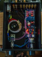
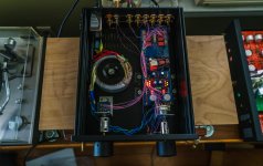
Your boxed Mez looks nice. Simply dark and purposeful with well integrated source selection lights. RegardsHere is the last one.
Hi,
I build my DCB1 almost a year ago. Everything is excellent. I pair it with a Chipamp lm3886. No complains.
I want to add a lightspeed attenuator. Do I connect it? at the exit of the DCB1, on the boards pins, before it?
Thanks,
I build my DCB1 almost a year ago. Everything is excellent. I pair it with a Chipamp lm3886. No complains.
I want to add a lightspeed attenuator. Do I connect it? at the exit of the DCB1, on the boards pins, before it?
Thanks,
Hi,
I build my DCB1 almost a year ago. Everything is excellent. I pair it with a Chipamp lm3886. No complains.
I want to add a lightspeed attenuator. Do I connect it? at the exit of the DCB1, on the boards pins, before it?
Thanks,
I have a similar question about the attenuator, I read somewhere that you put in on the input to the buffer. If this is the case doesn't the DAC or whatever is feeding this going to see the impedance of the pot not the buffer?
My DAC has digital volume so I'm going to build mine without volume but may add it later as the DAC is said to loose bits when the volume is well down.
Thanks
Pass DIY Addict
Joined 2000
Paid Member
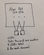
Thanks Eric, I haven't ordered the selector board as I'm only using the 1 input. Do you have a diagram of how you've implemented the ldr's.
So what about the impedance that the dac or other input See's, any idea what that is? My main reason for building this is to get a higher impedance for my DAC.
Cheers
So what about the impedance that the dac or other input See's, any idea what that is? My main reason for building this is to get a higher impedance for my DAC.
Cheers
You might consider Uriah Daley's "Clone Note" version - it has the adjustment of the series ldr for input/output impedances range, and the shunt resistors give the required attenuation and no need to closely match the ldrs - much more transparent/clearer sound than the basic 'Lightspeed'
As any volume control pot, stepper, etc produces a change in impedance (or a range of impedance dependent on attenuation) try the B1 buffer before the volume control and also after it, to see which suits your other components
You can look it up on www.buildanamp.com
As any volume control pot, stepper, etc produces a change in impedance (or a range of impedance dependent on attenuation) try the B1 buffer before the volume control and also after it, to see which suits your other components
You can look it up on www.buildanamp.com
Pass DIY Addict
Joined 2000
Paid Member
Here is the wiring diagram for the LDRs. My LDRs are a matched quad from Uriah.
Attachments
Last edited:
Thanks Eric, still not sure on the volume issue.... as im building this buffer mainly to take care of my impedance balancing issues, eg DAC requires hi impedance. Do I put the volume pot or whatever I end up with before the buffer or after it, on the output? May just go for a stepped attenuator.
Summary of system, DAC want to see hi impedance but my two amps in parallel are only 5k, too low to suit my pre....
Thanks
Summary of system, DAC want to see hi impedance but my two amps in parallel are only 5k, too low to suit my pre....
Thanks
Dear all, any chance we can replace the 8 2Sk170's used for the PSU with JFET's like J111/J113 as I have exhausted my 2SK's I can only use the matched remaining ones for the Buffer. In case we can replace, what Idss values could be ideal. I have a huge lot of J111's with Idss ranging from 3mA to 30 mA
- Home
- Amplifiers
- Pass Labs
- Mezmerize DCB1 Building Thread