That's a stepped attenuator.
All the components would need to be 0.1% or better.
The sums of components in the two balance halves would have to be 0.1% or better.
The resistances across the contacts would need to vary by an amount of less than that, that would cause more then 0.1% of mismatch in any of the sums of values.
It can be done, but it will need a lot of matching (=time)
Finally I did the hot-rod first stage and I'm very impressed, the bass are incredible, as well the sound stage are wider and deeper.
I'm using two 16 Ohm resistors in parallel, the DCB1 are now close to 200m to 210mA (The voltage across the resistor drops a bit) (The DCB1 is cold).
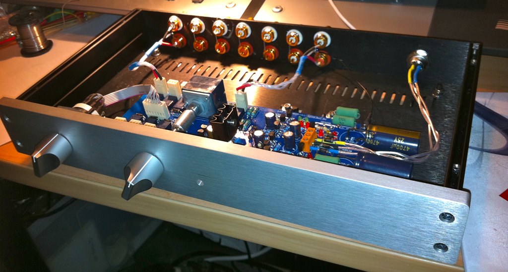
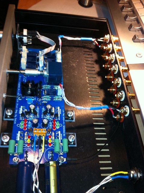
A photos of the "near to finish" Mezmerize:
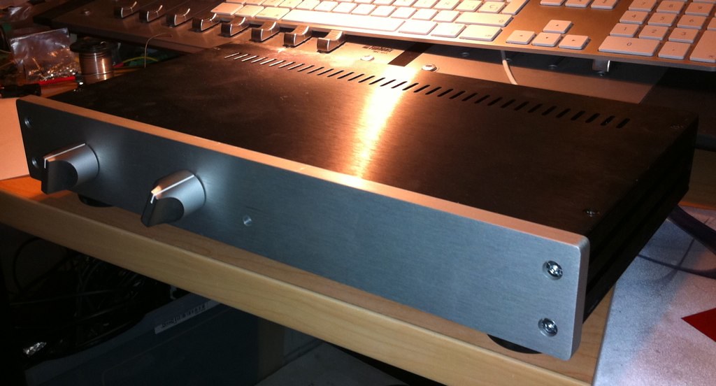
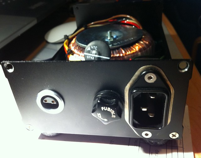
Thanks Salas!
I'm using two 16 Ohm resistors in parallel, the DCB1 are now close to 200m to 210mA (The voltage across the resistor drops a bit) (The DCB1 is cold).
A photos of the "near to finish" Mezmerize:
Thanks Salas!
Looks great Ramallo!
How warm does the bottom of your case get with the hot-rod (200mA)? I'm doing something very similar.
How warm does the bottom of your case get with the hot-rod (200mA)? I'm doing something very similar.
Thanks Salas!
Nice pictures, nice build. You are welcome, and enjoy.
Looks great Ramallo!
How warm does the bottom of your case get with the hot-rod (200mA)? I'm doing something very similar.
Is cold
 . The hottest
  part of the pre are the 7812 and the power resistors.
The bottom are a 3mm aluminum.
Indeed that is a lovely build Ramallo - may I ask what the case is?
Is a Hifi2000 case, 1NGXA347 modu
Hi Ram,
looks fantastic. Be proud and enjoy.
I am surprised at your remark "cold".
Using a 15+15Vac transformer and 200mA CCS there is some 8W of dissipation. That should not feel cold.
looks fantastic. Be proud and enjoy.
I am surprised at your remark "cold".
Using a 15+15Vac transformer and 200mA CCS there is some 8W of dissipation. That should not feel cold.
I guess 8 W of heat just "dissapears" on such a big metal bottom plate.
Its a sign that the (9)240's are making great thermal contact.
Measuring locally with a "temp gun" could reveal whats really happening
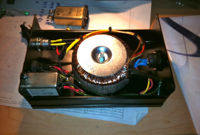
@Ram, why didn't you put the toroid together with the other stuff in one enclosure?
Jan
Its a sign that the (9)240's are making great thermal contact.
Measuring locally with a "temp gun" could reveal whats really happening
@Ram, why didn't you put the toroid together with the other stuff in one enclosure?
Jan
NO !!!!Its a sign that the (9)240's are making great thermal contact.
The exact opposite.
Bad thermal conductance will give what appears as a cooler running heatsink, while the devices are burning up inside.
A cool device is a good clue to good thermal conductance.
I don't think a (9)240 can be cold on the outside while they are burning on the inside at the same time.
Ram reported everything to be cool, so I assume his (9)240 are cool on the outside as well.
"A cool device is a good clue to good thermal conductance". I fully agree with that.
Jan
Ram reported everything to be cool, so I assume his (9)240 are cool on the outside as well.
"A cool device is a good clue to good thermal conductance". I fully agree with that.
Jan
an example of a bad thermal conductor to a device with air between it and the heatsink.I don't think a (9)240 can be cold on the outside while they are burning on the inside at the same time.
remove all the bolts holding the CCS devices to the base plate. Lift them ever so slightly from touching the base plate.
Do you think the case will be cold and the devices burning hot on the inside?
It's an extreme example but it shows why a cool or cold heatsink cannot be used to determine whether a device has adequate cooling.
It's the device temperature (Tc) that matters.
Hi Ram,
looks fantastic. Be proud and enjoy.
I am surprised at your remark "cold".
Using a 15+15Vac transformer and 200mA CCS there is some 8W of dissipation. That should not feel cold.
Maybe this aluminum chassis in more than enough for dissipate the heat (My "cold" is below 25ºC), I'm using a 12+12Vac transformer.
The mosfets are as cold as the chassis (finger test)
What is the voltage drop across the CCS mosFET Drain to Source?I'm using a 12+12Vac transformer.
How low will that Vdrop go if mains is at minimum tolerance?
What is the voltage drop across the CCS mosFET Drain to Source?
How low will that Vdrop go if mains is at minimum tolerance?
I'll measure tomorrow the voltage drop on the mosfets.
The voltage drop on the resistors:
http://www.diyaudio.com/forums/pass-labs/176723-mezmerize-dcb1-building-thread-12.html#post2433104
Now is down a bit 1.49V and 7,4 Ohm of measured resistance on both sides (The two 16 Ohm resistors in parallel), the offset remains the same.
I'll try with the variac down a 10% the mains for see (My regular AC is 230V).
Last edited:
ramallo, It is a nice build that serves as a guide for many of us.
Thanks Ed, have your leds inside 🙂
- Home
- Amplifiers
- Pass Labs
- Mezmerize DCB1 Building Thread