More "corrected" than Hans model? 🙂
George
Nope, Hans was exactly right. I just mentioned that as a reference to point out we had found what we were looking for in the M97. It's been a busy evening so didn't have a chance to remind myself who originally found this back in the 70s.
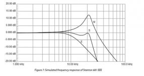
Just scanning the Van Raalte paper again and interestingly his combined electrical and mechanical response looks remarkably like your plot. This to me suggests that self resonance may have been the reason so many people think there is mechanical resonance in the audio band. Certainly your data fits that and suggests as was thought some pages back that the M97 doesn't have the laminated core of the V15V.
OTOH a 2dB shelf is easy for your miniDSP to correct.
I may have missed something but seems to me some dots have been joined today 🙂
Attachments
I'm even more lost now........Hi Bill,
This is 100% the same as what I did, only the values are different.
Hans
View attachment 610024
This is meant to be a model of a 2-wire impedance of a passive wound coil.......??? What's the physical meaning of it, and where has the self capacitance gone ?
Confused, yoda is...........
LD
What's the physical meaning of it ?
Or, put another way, how would one physically implement this transfer function, using only parts found within that cartridge coil arrangement..........?
Interesting, and I think that's the crux as to whether it is real or somehow an artefact of testing. So far, the penny hasn't dropped as to any mechanism for it.
George, what exact cartridge model is it ?
LD
OK now I am confused, to me what Hans has modelled to match the response George has measured matches the self-inductance model that others have discovered over the last 40 years. What have I missed?
I think if one looks at Hans' model at face value, it suggests there is a frequency dependant lossy part, and a non-lossy part of the coil.
Putting aside how and why that might be for now, when acting as a generator, thesis is at least part of the coil exhibits increasing hf loss. Which seems reasonable. Looking in to the coil, impedance will fall/shelve, at least in part, and become lossy at hf.
Then the sense of the test result is inverted here, versus true generator output - in real playback there should be a dip, not a peak, in output, I think. And that makes a lot more physical sense to me......
LD
Last edited:
I think the correct model will not only describe a cartridge as a 2 pin network looking in, but also as a generator looking out, as well as having a satisfying physical explanation.OK now I am confused, to me what Hans has modelled to match the response George has measured matches the self-inductance model that others have discovered over the last 40 years. What have I missed?
Perhaps, historically, they stopped after achieving the first step.........?
LD
Last edited:
Given by the time they published phono stages were all 47k+XpF was probably swimming upstream to worry about people doing odd things ! 🙂
In short, there still seems a lot to unravel.Then the sense of the test result is inverted here, versus true generator output - in real playback there should be a dip, not a peak, in output, I think. And that makes a lot more physical sense to me......
LD
A Cart is a pool full of mysteries.
But as Einstein once said: Not everything that counts can be counted.
So finding a physical explanation for every single issue might be difficult.
The good news is that with Aurak's virtual input, the usual resonance of Lcart, cable capacitance and 47K loading has been eliminated, enabling a much better view now on other parameters.
I'm looking forward to seeing new recordings from George taken with the anti-riaa network, without the ferrite beads and if possible with a better input amp as the LF412.
Hans
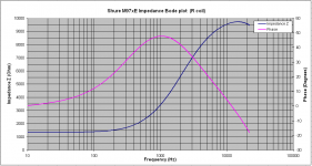
George, what exact cartridge model is it ?
Shure M97xE
I did an impedance sweep.
Here are the results for the R coil.
George
Attachments

It's the result of the same mechanisms that require Julian Wright's 'fudges' for the inductance of a speaker voice coil.Or, put another way, how would one physically implement this transfer function, using only parts found within that cartridge coil arrangement..........?
Interesting, and I think that's the crux as to whether it is real or somehow an artefact of testing. So far, the penny hasn't dropped as to any mechanism for it.
AES E-Library An Empirical Model for Loudspeaker Motor Impedance
I think all the better speaker design/analysis programmes allow this to be measured and/or specified.
The Shure laminated pole pieces go some way to reduce this & alleviate the nasty effects.
I don't think the Rod Elliot model is '100%' correct. The phase won't be quite right ... which is why Julian developed his model. You'll have to read the paper as all this was more than 25 yrs ago and I might be pontificating from the wrong orifice.
I worked with Julian at Celestion in da previous Millenium 🙂
_______________________
If I may be so bold to interrupt this discussion of theoretical frequency response ... I don't think you can do sensible work without, at some stage, using a Test Sweep Record.
Is anyone going to try running 2 sweeps, one after another, and comparing them to check my assertion that records need time to 'recover' 😀
Or have I frightened everyone from ruining their precious Test Records 😱
_______________________
I see the Aurak(s) do basically what I suggested .. which is to run the cartridge into a Virtual Earth and then compensate using analogue stuff. It falls down in using evil resistors in series with the cartridge to get some pre-determined pole to match the analogue EQ.
I think Bill has the required tools to do ...
cartridge straight into virtual earth (balanced or otherwise) and DSP to do the required EQ ... RIAA, cartridge and any other effects.
My caveat is that you should be using IIRs (Digital Filters as God intended) instead of EVIL FIRs.
AES E-Library Simple Arbitary IIRs
But I haven't read Guru Wurcer's Linear Audio article on EVIL FIRs for RIAA. (Beach bums can't afford books & stuff.) .. so may reserve judgement .. but only on stuff from true Gurus. 😀
Sorry Bill, you still have to use your Test Record. 😉
Last edited:
interesting, the cart I was planning to use with Aurak, b&o mmc2, needs no 'evil' resistor in series.
Hi Scott
Which Denon?
Back at you, was that a straight-up DL-103 (vs S or R or...)?
When I fitted the DL-103 on the SME3009 II Improved (a light but not very light arm), I added weight at the headshell (*).
Conequently I had to add mass at the counterweight and the bias weight. I used plasteline (ease of use, works also as a damping element)
I like the way you distributed the weight. There is a putty-like material calked Duxseal which I have heard about and used since the 1970's. It has a much higher density than plasticene, and contains a lot of fibrous material which aids damping. Sadly it does not come in vibrant colors.
did it while monitoring the waveshape when reading the highest modulation velocity 300Hz track of HFN test record.
Of course you did. This is why people take you seriously here. You actually build things and measure them, and the things you measure are meaningful. And when you get something wrong you admit it and fix it. Hi
But I haven't read Guru Wurcer's Linear Audio article on EVIL FIRs for RIAA. (Beach bums can't afford books & stuff.) .. so may reserve judgement .. but only on stuff from true Gurus. 😀
Sorry Bill, you still have to use your Test Record. 😉
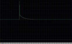
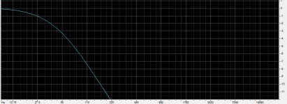
At 48k 3120 points trivial with today's processors. Notice min-phase and yes it goes to DC with no ripples. Directly computable by one inverse FFT with pre-ringing greatly reduced by a simple trick. 3120 points to <1/2 a 24bit LSB without windowing. I assume Audacity uses Parks-McClellan which is linear phase and not as good at >8000 points.
EDIT - That's the impulse response and a zoom of the low frequency end of its FFT (-3dB @ 50.05 Hz).
Attachments
Last edited:
Which I have a feeling the M97 doesn't have and we might just be homing in on. AT does and the Ortofon split pole generators gives the same benefit.The Shure laminated pole pieces go some way to reduce this & alleviate the nasty effects.
I don't think Rod considers his model 100% correct, just a lot better than the standard one.I don't think the Rod Elliot model is '100%' correct. The phase won't be quite right ... which is why Julian developed his model. You'll have to read the paper as all this was more than 25 yrs ago and I might be pontificating from the wrong orifice.
As does George. However right now I'm still at the 'all the gear and no idea' stage. 🙂I think Bill has the required tools to do ...
What interests me to experiment with when I get time to get a working sim is whether some carts have a sweet spot so you can use the loading to give you the 500Hz pole for free then all the rest digital. You end up need to add about 12dB digital gain, which will impact noise performace a tiny bit, but feels like its worth my time to investigate.cartridge straight into virtual earth (balanced or otherwise) and DSP to do the required EQ ... RIAA, cartridge and any other effects.
Hey this gives me an excuse to buy a new test record. I'm happy 🙂Sorry Bill, you still have to use your Test Record. 😉
😱 Du.uh! I'm still using a 1980's compiler for my own serious stuff and can't do bigger than 8K FFTs 😡 Don't laugh Guru Wurcer. 😱At 48k 3120 points trivial with today's processors. Notice min-phase and yes it goes to DC with no ripples. Directly computable by one inverse FFT with pre-ringing greatly reduced by a simple trick. 3120 points to <1/2 a 24bit LSB without windowing. I assume Audacity uses Parks-McClellan which is linear phase and not as good at >8000 points.
I've tried on 3 occasions this Millenium to download a modern compiler (an interminable process) but was foiled by computer failure each time from my eBay specials 😡
There's no need for fancy stuff like Parks-McClellan. Circa 1990, I developed my own big (??) FIR design method .. min-phase, no ripples bla bla .. which is why I want to know the nitty gritty of Guru Wurcer's method.
Yes the Audacity FFT filter is truly EVIL linear phase.
Guru Wurcer, Wayne Kirkwood found a couple of IIR and IIRC, at least one FIR RIAA EQ on some DAW to be accurate, min-phase bla bla. It's buried deep in one of his balanced phono system threads. He designed & built these systems to do de-clicking and EQ digitally. I'm getting better at these TLAs and FLAs 😀
________________
Simple Arbitrary IIRs points out that modern processors have dedicated instructions to do big EVIL FIRs efficiently. Most of the better Room EQ programmes use them.
Does anyone know if the MiniDSP and other cheapo boxes do too?
More importantly, can these boxes do efficient arbitrary IIRs with loadsa (or a few) arbitrary feedforward & feedback coeffs?
There is an inescapable EVIL of FIRs. Big FFTs lead to BIG DELAY .. OK for home playback but not for microphones and/or live sound.
Last edited:
Bill, the 318us (500Hz) is a ZERO, not a pole. At best, with virtual earth amp & moving magnet, you could achieve a 75us (2122kHz) pole.What interests me to experiment with when I get time to get a working sim is whether some carts have a sweet spot so you can use the loading to give you the 500Hz pole for free then all the rest digital.
I think a few people, eg mcspack, have said that their cartridge had the correct pole without EVIL series resistors for the standard Aurak EQ .. which might not be expecting a 75us pole.
I would take all this (really good) theoretical pontificating with a large pinch of salt and get a test record.
Last edited:
50Hz. I must stop posting very late at night when over tired. Currently for many MM the pole is around 150Hz. But like I said this is a playtime thing for me as and when.
Having thought about it, seems most likely that the non-ideals in coil impedance looking into the coil as a 2-pin network are hf losses associated with eddy currents.
Here's a couple of very good links to Lloyd Dixon's writings on the physics and practicalities involved in eddy current losses in transformers, which I suppose is a close cousin of a cartridge generator, a 'primary-less' transformer.......
I'm trying to form a model of a generator that works both in terms of losses as a generator, and impedance as a 2-pin coil looking inwards.
http://www.ti.com/lit/ml/slup197/slup197.pdf
http://www.ti.com/lit/ml/slup123/slup123.pdf
These are good resources IMO. Wrapped up in there are physics of core laminations, winding methods, skin effect, faraday shields.
Enjoy!
LD
I'm not sure you can dream up a 'linear' LTspice 2-pin model for this. If so, Julian would have done it for speaker voice coil inductance.Having thought about it, seems most likely that the non-ideals in coil impedance looking into the coil as a 2-pin network are hf losses associated with eddy currents.
...
I'm trying to form a model of a generator that works both in terms of losses as a generator, and impedance as a 2-pin coil looking inwards.
IIRC, his paper explains why it isn't possible.
Maybe if you add some different passive components to go with the usual Resistance Inductance Capacitance in LTspice 😀
His 'fudged values' were calculated and tabulated for use in xover design software.
They were originally derived from FFT impedance plots after all 'other' factors had been removed / accounted for.
As I said, all the good speaker design programmes use his 'model'
Any AES members who could provide Lucky with a sneak view of Julian's paper?
Speakers are similar in that there is a generator too: the voice coil is in motion of course. But I'll give it a shot to come up with a 'correct form' 2 pin model for a cartridge, including the generator. It's said to be 'impossible' because eddy/magnetic losses are heavily non-linear, but even an approximation would be good here.I'm not sure you can dream up a 'linear' LTspice 2-pin model for this. If so, Julian would have done it for speaker voice coil inductance.
I suspect not all cart generators exhibit such losses in the audioband, otherwise my OM40 would not behave so well with TI loading and the Aurak as drawn. But the Shure cart George has characterised appears to, for example. But then not all carts tolerate TI loading well in any event, IME.
Anyways, we need a challenge 😉
And understanding cartridge limitations might be informative about cartridge choice. As Hans posted, what we might be seeing more clearly now with TI loading appears to be other non-ideal characteristics of the cartridge generator, which is pretty interesting per se, I think.
Otherwise, it's another trip to the British Library for me........Any AES members who could provide Lucky with a sneak view of Julian's paper?
LD
- Home
- Source & Line
- Analogue Source
- mechanical resonance in MMs