In that test set-up, transimpedance loading should provide a near perfect way of observing self-resonance of the coil, I think.Lucky, let’s see how the low input impedance will affect the measurement.
My test records go only up to 20KHz unfortunately.
Question: If I play the test record at 45RPM, will the 20KHz increase to 27KHz [27=20*(45/33.3)] ?
Yes, playback at 45rpm of test records intended for 33rpm can be a good way of generating frequencies up to 27kHz. However, the RIAA curve will be wrong, so results will need correction for the error arising. Real playback like this won't show coil-self resonance, which is what you want presumably because it is real playback performance.
LD
Bill,Lazy question as I haven't yet found time to work this out for myself. Do we have a feel for the sort of noise performance the front end op-amp needs and are we optimising for current or voltage noise? This is for the parts box raiders who want to try it out.
Just a quick check for the OPA1632 circuit in posting #408 with the 580mH and 460 Ohm Cart, I got the following results:
When making the first 1632 amp input voltage and current noise free, A-weighted Noise is 476nV.
Looking for a 3 dB noise increase, I had to use 7nV/rtHz voltage noise with no current noise and go to 0,45pA/rtHz current noise with no voltage noise.
The 1632 has 1.3nV/rtHz voltage noise and 0.3pA/rtHz.
Noise with both noise sources on is 574nV and with zero voltage noise 567nV.
So current noise in this case seems indeed to be the dominant noise contributor.
When looking for alternative amps for this Aurak design, I would say: stay below 5nV/rtHz and 0.3pA/rtHz > 1Khz
Hans
Last edited:
Thanks. Looks like the TLE2074 I have a pile of just fails. 2.8fA/rtHz but 12nV/rtHz. I should start learning how to drive LTspice. Not used spice for 30 years as other stuff got in the way.
Putty is bad. Keep it in a separate locked room away from TTs, carts, pets, food, kids etc etc.....
Lucky, you are full of surprises. What putty is bad and why?
Is plasteline bad?
However, the RIAA curve will be wrong
May I ask why?
Real playback like this won't show coil-self resonance, which is what you want presumably because it is real playback performance.
Yes. I want to confirm this
George
Those caps as sketched provide a roll-off that compensates for very slight lift in the upper hf audio band associated with specific mech resonance in the carts I use, and also underwrite stability in protototype layouts. Without them, subject to layout, transfer characteristic is good for a few hundred kHz, in principle.
LD
I thought as we were discussing resonances again time to pull this post from a few backs back out as it relates to how we do the final tuning. I will have PEQs to burn, but for the all analog brigade what sort of magnitude are we talking about. From the sims appears to be a dB here and there?
May I ask why?
The RIAA time constants will also be shifted. There are unequalized test LP's such as the constant velocity STR120 which will just shift up to a new constant velocity. Wow up to 67.5kHz.
The RIAA time constants will also be shifted. There are unequalized test LP's such as the constant velocity STR120 which will just shift up to a new constant velocity. Wow up to 67.5kHz.
OK thanks. I’ll try to hack a DD I have here to see how fast I can make it spin.
In that test set-up, transimpedance loading should provide a near perfect way of observing self-resonance of the coil, I think.
Here we are 🙂
George
Attachments

Here we are 🙂
George
When this is recorded with your recently breadboarded Aurak, you have my compliments, great result.
I'm curious to hear the explanation behind the dip.
Since nothing is moving, is the cause of pure electrical nature ?
Hans
Thank you, George.Here we are 🙂
If you haven't already, would you please do a run with just a resistor equal to the cartridge coil resitance, so we can see the transfer function of your new Aurak ?!
Seems there's something odd with the general hf audioband lift, and would be good to find it methinks.
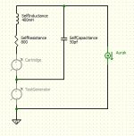
Yes, I think there's no surprise you clearly see the coil electrical self-resonance in that method. I've attached a schematic/topology sketch that I think illustrates why you see this with the external generator but should not in real playback.
In the sketch, there are two voltage separate voltage sources: one is the cartridge generator, the other is your external test generator. The current sensor, Aurak, has zero impedance, and we are interested in that current in Aurak when we use only one of the two voltage sources. I think it's easy to see the difference, and that, when the test generator is used, self-resonance of coil applies. Whereas, when the cartridge generator is used, self-capacitance is shunted by Aurak's zero input impedance so there should be no coil self-resonance.
PS: Oops, sorry I misdrew the sketch - appols for confusion, kindly ignore - I'll repost thx LD
PPS: Having some kind of mind melt, appols, I think the sketch is correct after all......... I'll go have a coffee !
LD
Attachments
Last edited:
George,
It would be nice if you could show a copy of the exact circuit diagram that you are using, especially knowing the bandwidth reducing caps is important.
And also the details of your Cart, for Lcart and Rcart.
With all this info will it be possible trying to match the simulations in LTSpice to your measurements.
Just inserting a 50pF cap in parallel to the cart gives a different image with a much deeper dip as you have recorded.
When placing instead 200KOhm//50pF parallel to the cart, gives a dip of -4dB like you have, but without the shoulders before and after.
See both sims below.
Hans
Presumably this is SE and using George's test setup.........? In which case, seems reasonable to me and I agree with your comments.See both sims below.
There is no way to connect George's test setup without observing coil self-LCR, for reasons we discussed previously, of course.
LD
BTW, I think self-LCR resonance of MM/MI coils is uncharted water AFAIK, and pretty interesting per se. From George's previous results, seems to vary greatly between cart manufacturers too.
LD
LD


A combo of 27pF//220K in series with 56K, will bring the sim even closer to Georges recording, with a dip at 34Khz of -3dB and a 4.5dB peak at 130Khz.
Hans
Hans
George,
Since you didn't have the opportunity yet to respond to my questions, I simply went on.
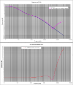
I was very well able to reproduce quite accurately your recording with an external generator, see below on the left side.
However when simulating this circuit with the internal generator, FR was not flat as shown at the right side.
So your input resistor may not have the right value, causing the shoulder at the left side of your dip.
Hans

Since you didn't have the opportunity yet to respond to my questions, I simply went on.
I was very well able to reproduce quite accurately your recording with an external generator, see below on the left side.
However when simulating this circuit with the internal generator, FR was not flat as shown at the right side.
So your input resistor may not have the right value, causing the shoulder at the left side of your dip.
Hans
Last edited:
Sorry for not responding so far.
Hans and Lucky, thank you for your interest, particularly for the sim efforts.
Hans, don’t spend your time again trying to chase stupidity.😀
I had connected both pre channels at the generator out, L directly, R in series with the Shure cartridge for to monitor L out and R out on the scope simultaneously and when the time came for measurements, I forgot to disconnect L from the generator.
So, the input impedance did change and the diagrams in post # 487 were (unintentionally) misleading.😱
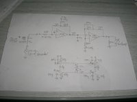
I attach the schematic of what I have built and the connection used to take the measurements (only one channel connected this time 🙄)
Lucky, I am going to take measurements with an R in place of the cartridge
George
Hans and Lucky, thank you for your interest, particularly for the sim efforts.
Hans, don’t spend your time again trying to chase stupidity.😀
I had connected both pre channels at the generator out, L directly, R in series with the Shure cartridge for to monitor L out and R out on the scope simultaneously and when the time came for measurements, I forgot to disconnect L from the generator.
So, the input impedance did change and the diagrams in post # 487 were (unintentionally) misleading.😱
I attach the schematic of what I have built and the connection used to take the measurements (only one channel connected this time 🙄)
Lucky, I am going to take measurements with an R in place of the cartridge
George
Attachments
Hey everyone, What is the best way to utilize one of(all?) of these TI circuits for mono playback? Strap a stereo cart at the headshell? a simple summing switch in the pre? Parallel or Series? Hope I havn't started something crazy :-/
- Home
- Source & Line
- Analogue Source
- mechanical resonance in MMs