MCs have more 'output' than most MMs.
This is exactly what I use to calculate 'power output'. V^2 / Rdcif anything it is typically the other way round, if one considers total power available from the generator into it's own impedance (s/c).
The transducer doesn't have to deliver this power but it determines the potential S/N. You don't have to short the transducer to realise this S/N either though transimpedance is one good way to do it.
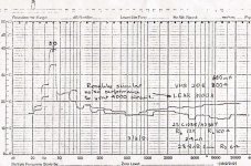
Here's an example (not transimpedance) measured with our steam powered B&K 2307 & 1/3 8ve filter set.
The B&K 2307 chart recorder has slipped by 1 tooth so 50Hz (hum) appears at 40Hz. 1dB/division. I await with bated breath for Doug to show us how to get unmeasurable hum with unbalanced stuff 🙂
The MM is an Ortofon VMS20E. The Ortofon MC, either MC20-2 or MC10. The MC preamp is set for very high gain 28.8dB so if adjusted for equal loudness from the 2 cartridges, the noise advantage of my little circuit is even better.
What this shows is that with the common noise weightings, the MC with this circuit is at least 3dB quieter than the MM into a good MM RIAA preamp. The character of the noise is nicer too. With RIAA, MM noise is whitish while MC is redder than pink and less obtrusive.
If we use Doug's Virtual Reality Input Z, you can claw back 1dB and a bit for the MM but the MC with this circuit would still be quieter.
Of course, you need a very quiet MC preamp to realise this and the measured 1980 device is surprisingly still the quietest such beast in the universe .. 0.28nV/rtHz.
Wayne has dug up some even better devices so I might do an even simpler device this Millenium with better performance. 😎
______________________
Most MCs have higher 'power output' compared to most MMs.
But MMs are further hobbled cos their inductance doesn't allow their 'power output' to be realised fully. A Transimpedance Amp may be the closest.
Attachments
Last edited:
I've already answered Guru Wurcer on this and agree with you and him that any electromagnetic damping is insignificant.So although Bli applies, forces arising are trivial, and there is no mechanical damping associated with electrical load of the generator.
Can I ask you to do a long FFT Spectrum Analysis of repeated playings of a Test Record too.I have never found difference, non-repeatability, nor damage arising, from back to back playback of test records.
Please specify what cartridge/arm/VTF etc too.
My experience goes back 35+ yrs but SHURE V15 III, IV and some other good cartridges were extant then and would have at least as 'little' or as 'much' effect on record wear as any modern stuff ... now that V15 V is Unobtainium.
_________________________
In case it wasn't obvious, the horizontal lines ...
_________________________
.. in my #214 post denote separate points. eg the 'power output' point has nothing to do with the electromagnetic damping stuff .. except that certain MCs have the highest chance of showing something cos their efficiency .. but even they don't show anything significant.
_________________________
I'm fully prepared to admit everything this beach bum knows is wrong. It's quite liberating to be able to pontificate from the wrong orifice without any serious (or minor) consequences. 😀Richard you can't play here unless you are willing to admit everything you know is wrong.
Last edited:
Funny that CD4 quadrophonic records are still playable after all these years, with HF content up to 40kHz. You would have thought 3 plays and they would be useless. Or were test records made of cheese 35 years ago?
No, in my case I think there are visual artifacts from the software doing a sinc interpolation for display of a squarewave. Here is a 500-50kHz frequency sweep at constant velocity, the bump at 34 seconds is at around 13kHz with the sweep in fractional decades per second. With some imagination one can see the TL effects especially in the lower channel but no sharp resonances. I mentioned yesterday that my recorder aliases so there is actually information here out to 50kHz at 96kHz sampling.
I have transferred your Grado's 500 to 50Khz plot as accurate as possible into a version with a dB and frequency scale.
Here is the result, showing a 6dB/oct roll off from 13Khz upwards.
Hans

I have transferred your Grado's 500 to 50Khz plot as accurate as possible into a version with a dB and frequency scale.
Here is the result, showing a 6dB/oct roll off from 13Khz upwards.
Hans
View attachment 604287
Thanks Hans for the effort, I would think the slow drop to 5k would have a signature. IIRC I got similar results with the fancier wooden Grado in an MMT arm and on a VPI table. If I get a chance I'll try and do a Python script to do this in 1/10 octave bands averaging the level and frequency and see how it compares.
Last edited:
I'm fully prepared to admit everything this beach bum knows is wrong. It's quite liberating to be able to pontificate from the wrong orifice without any serious (or minor) consequences. 😀
Thanks for taking a little friendly kidding. When Lucky was able to critique results from B&K it really got my attention.
VERY smart people at MIT had the same misconceptions. They reinvented YOUR pre-amp BTW and used it on an old RCA 44 (transformerless) IIRC and approached us to integrate it for the MC phono market. The angle was damping of the stylus/vinyl interface as an analog for the ribbon/air interface.
I think I have a heavily used Monster Alpha 1 somewhere I could use my new USB microscope toy to image the tip as I apply a signal to the leads. Anyone taking bets on what I will see?
Another data point optical/strain gauge cartridges have identically zero reciprocity so the stylus/cantilever/vinyl interaction is purely mechanical.
EDIT - Your pre-amp noise performance is solely in the ken of the transistor manufacturers these designs send folks scrambling every time a low rbb transistor is discontinued/discovered. Too bad it's not financially advantageous to just kill this beast once and for all, make a complimentary pair that has .1 Ohm rbb and has no use but in ribbon mics and Ortophon cartridges.
Last edited:
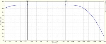
Since the SE and Balanced Aurak diagram was performing so well at first attempt, I changed the very fast LT6202 amps for the more mondain OPA1642 Fet amp.
Bandwidth is a bit less now, -1dB at 227Khz, but still more than excellent. When I add all 10pF, 22pF and 1.5nF caps being included in LD's and Brinkman's diagrams, it's obvious that these caps are castrating the perfect transfer function to -1dB at 27 Khz and should not be used.
The OPA1642 is stable as a rock as doesn't need these caps.
I also measured an excellent 71.8 dB A-weighted S/N ref 5mV@1Khz and notice that this figure includes the Cart connected !
Usually S/N is specified with a short circuited input, giving a much better figure.
Hans
As I did this circa 1980 with a travelling microscope, my bet is on exactly what Bl i predicts ... which is sweet 'f**k all' ... unless you smoke the Alpha of course 😱I think I have a heavily used Monster Alpha 1 somewhere I could use my new USB microscope toy to image the tip as I apply a signal to the leads. Anyone taking bets on what I will see?
You forget the EVIL resistors!Your pre-amp noise performance is solely in the ken of the transistor manufacturers these designs send folks scrambling every time a low rbb transistor is discontinued/discovered.
Many of you know I like resistors. They have much less noise & distortion than other stuff. But for certain applications, resistors .. well they resist the flow of electrons. In my circuit, no resistors get in the way of the signal. Only the output resistor affects the sound. Transistors on the other hand, transist .... 🙂
My new bit of learning was LD's assertion that cantilever modes were the answer to Life, the Universe & Everything.VERY smart people at MIT had the same misconceptions. They reinvented YOUR pre-amp BTW and used it on an old RCA 44 (transformerless)
The real expert on this topic is Les Watts who did the M24 CD4 cartridge for SHURE and went on to do V15 V IIRC.
I'm getting drips & drabs from senile memory but I now think his AES paper model includes both vinyl compliance AND cantilever modes. His patented method was to get the 'resonance' higher using 'cheapo' bits on M24.
So both are important.
BTW, I stole my circuit from another clever guy ... but if I take someone's circuit, throw out some bits, change a few resistors and get more than 10dB better noise & less THD ... I think I'm entitled to claim I understand his circuit better than he does. 🙂
CD4 decoders were designed to 'work' even if the supersonic carrier signal was badly degraded. I didn't say the HF disappeared on one play. But it was certainly noticeable with the 0.2dB resolution of the 50dB pot on a steam powered B&K 2307 chart recorder circa 1980.Funny that CD4 quadrophonic records are still playable after all these years, with HF content up to 40kHz. You would have thought 3 plays and they would be useless. Or were test records made of cheese 35 years ago?
Let's wait for Gurus Wurcer & LD to produce some measurements with 21st century tools
Can't guess, but for sure the simulation of the circuit as sketched should have a f response (transfer function) which looks like this, pretty much ideal...........I simmed the circuit in Post # 204 by luckythedog & no matter what value i give for R, i always get a depressed mid ! What am i doing wrong ?
I just re-ran it.
It's devised so that total cartridge resistance (coil plus external series resistor R) in ohms needs to be twice the cartridge inductance in mH. Cute, I still think.
LD
Attachments
Agreed. These are MM carts too, hard to imagine perhaps.......Since the SE and Balanced Aurak diagram was performing so well at first attempt, I changed the very fast LT6202 amps for the more mondain OPA1642 Fet amp.
Bandwidth is a bit less now, -1dB at 227Khz, but still more than excellent. When I add all 10pF, 22pF and 1.5nF caps being included in LD's and Brinkman's diagrams, it's obvious that these caps are castrating the perfect transfer function to -1dB at 27 Khz and should not be used.
The OPA1642 is stable as a rock as doesn't need these caps.
I also measured an excellent 71.8 dB A-weighted S/N ref 5mV@1Khz and notice that this figure includes the Cart connected !
Usually S/N is specified with a short circuited input, giving a much better figure.
Hans
View attachment 604347
Those caps as sketched provide a roll-off that compensates for very slight lift in the upper hf audio band associated with specific mech resonance in the carts I use, and also underwrite stability in protototype layouts. Without them, subject to layout, transfer characteristic is good for a few hundred kHz, in principle.
LD
Last edited:
TL/cantilever thesis explains the two observable resonant response peaks as harmonic modes of cantilever vibration, ie there's no need for vinyl compliance at all. Indeed, 'both' would not fit, because for sure there are not three peaks, and the resonant modes of the cantilever must be there IMO.I'm getting drips & drabs from senile memory but I now think his AES paper model includes both vinyl compliance AND cantilever modes. His patented method was to get the 'resonance' higher using 'cheapo' bits on M24.
So both are important.
Absence of vinyl compliance, I think, comes back to the matter of jolt, and how vinyl behaves when exposed to very short duration of high local force. Stylus/groove interaction is widely assumed to be elastic, but there's no basis for that, and I doubt it, for good reasons. Most likely rigid, the issue is more whether vinyl can be permanently or temporarily dented, but again there is no evidence for that either. So, rigid vinyl that isn't indented seems by far the obvious and simplest explanation to me.
Then the matter of apparent vinyl compliance can be wholly explained by cantilever flex - I simply don't see a contradiction, do you ?
Thanks for the pointers, a trip to the British Library to find Watts AES papers is coming on.....unless they involve the inertial damping ideas already discussed ?
LD
Last edited:
The clearest evidence of 'vinyl compliance' was when the industry moved from Shellac to Vinyl. The resonance of some 'good' cartridges moved into the audio bandwidth.TL/cantilever thesis explains the two observable resonant response peaks as harmonic modes of cantilever vibration, ie there's no need for vinyl compliance at all.
There's also differences between lacquers & the final stamped vinyl.
I think someone mentioned this either in this or some other long winded thread.
They also mentioned the LEAK pickup which was the last cartridge we designed & made commercially. There were loadsa experimental models up to the early 80s which never passed Marketing 😱
________________
You going to do 21st century Spectrum Analysis of subsequent plays of a Test Record?
I can't get the steam in Cooktown to run a B&K 2307 even if I had one ... let alone the Test Records & vinyl playback system 🙂
I simmed the circuit in Post # 204 by luckythedog & no matter what value i give for R, i always get a depressed mid ! What am i doing wrong ?
Showing us the detailed circuit diagram you are using would be a big help including how you implemented an inverse Riaa curve.
Hans
Since the SE and Balanced Aurak diagram was performing so well at first attempt
, ...
I also measured an excellent 71.8 dB A-weighted S/N ref 5mV@1Khz and notice that this figure includes the Cart connected !
These look like Transimpedance amps.Agreed. These are MM carts too, hard to imagine perhaps.......
So am I'm right in guessing this would give even better S/N on MMs than Doug's Virtual Reality Input Z? 😀
Perhaps, and...... the stylus, cantilever and suspension changed too......The clearest evidence of 'vinyl compliance' was when the industry moved from Shellac to Vinyl. The resonance of some 'good' cartridges moved into the audio bandwidth.
I have no way of verifying. However, IME there's no difference between many and various different manufactured vinyl......There's also differences between lacquers & the final stamped vinyl.
There can be significant LF spectral differences if one removes a record from the platter between tests, then replaces it randomly, due to different eccentricity and vertical run out. That, plus a certain random element to headshell stability in any event, is all I've clearly noted about repetitive playback over the years. Lf mechanics is fairly pervasive in effect though, and I came to the conclusion that no two playbacks are exactly the same, mechanically, because there is a random butterfly element to headshell movement and the motion is complex.
LD
The clearest evidence of 'vinyl compliance' was when the industry moved from Shellac to Vinyl. The resonance of some 'good' cartridges moved into the audio bandwidth.
There's also differences between lacquers & the final stamped vinyl.
I think someone mentioned this either in this or some other long winded thread.
Only reference I have seen to the that is the stereophile interview with John Crabbe which YOU posted on 11th Feb...
IIRC, that is consistent with Paul Miller's measurements on his Avtech website, and what I can recall of discussions from a few years back as to the causal nature of this profile.I have transferred your Grado's 500 to 50Khz plot as accurate as possible into a version with a dB and frequency scale.
Here is the result, showing a 6dB/oct roll off from 13Khz upwards.
Hans
View attachment 604287
LD
My bad the AT-440 shows it as well
http://www.milleraudioresearch.com/download2011/reports/mar11/ortofon_2m_black_mm.html
http://www.milleraudioresearch.com/download2008/reports/oct08/audiotechnica_at440mla_mm.html
But the 440 is impressive enough that I am really tempted to swap my Benz Micro for the AT-150MLx I have as my main cartridge..
- Home
- Source & Line
- Analogue Source
- mechanical resonance in MMs