I don't see how measuring 30 cycles would fix the issue described. The error may be smaller, but in principle it is still there, no?
The crux of the thing is to measure over a cycle of the 100Hz; even 20 cycles of the 1kHz give an error as shown in the lower graph.
But if you use a pure single freq signal, you can measure over a single cycle with no issues.
Jan
The crux of the thing is to measure over a cycle of the 100Hz; even 20 cycles of the 1kHz give an error as shown in the lower graph.
But if you use a pure single freq signal, you can measure over a single cycle with no issues.
Jan
I don't see how measuring 30 cycles would fix the issue described. The error may be smaller, but in principle it is still there, no?
The crux of the thing is to measure over a cycle of the 100Hz; even 20 cycles of the 1kHz give an error as shown in the lower graph.
But if you use a single freq signal, with or without harmonics, you can measure over a single cycle with no issues.
That's how I understood it.
Oh yes, better accuracy, etc. It is preferable, no doubt, if you have a sequence of 30 cycles... but sometimes, you don't.doesn't work that easily in real life.
Far better to just measure 30+ cycles and window then you don't need to worry about sampling rates, noise etc
I don't see how measuring 30 cycles would fix the issue described. The error may be smaller, but in principle it is still there, no?
The crux of the thing is to measure over a cycle of the 100Hz; even 20 cycles of the 1kHz give an error as shown in the lower graph.
But if you use a pure single freq signal, you can measure over a single cycle with no issues.
Jan
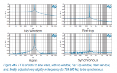
In this specific case the waveform is periodic over 10 cycles of 1kHz so it would be periodic over 30 cycles also. But in the general case the trick is windowing. FFT of a non-periodic signal is useless without a window. In this case it's 1k + 75Hs (orange) or 100Hz (blue) and an integer number of 75Hz periods do not fit into 30ms, so the FFT is a mess.
But application of a window function (here Kaiser 12 on the same signal) allows to pretend the signal is periodic by smoothly fading both edges of the acquired data to zero. And then it works. FFT noise floor is slightly elevated but non significant (-150dB...)
If the DAC clock (generating sinewave) and the ADC clock (acquiring it) are not synchronized then it is not possible to acquire an integer number of periods, it will always be an unknown fractional number because the sample clocks are not the same. In this case the usual method with windowing is the only way... and synchronous measurements are not possible, which is a shame, because they're damn useful.
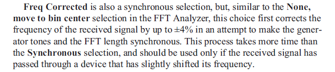
I just reviewed how AP does it in my 2722. Synchronous FFT has preference, but you can also select to slightly move an incoming signal frequency to make it synchronous with the FFT analysis.
The other option is to move the signal frequency slightly so it falls in an FFT bin center.
Jan
The other option is to move the signal frequency slightly so it falls in an FFT bin center.
Jan
Attachments

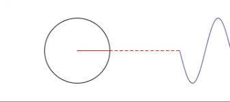
A sinusoid is formed by rotating a vector of constant length (determines the peak value of the voltage) and with a constant angular velocity (determines the frequency of the signal). In order for additional spectral components to appear in the spectrum of the sinusoid, the vector must convulsively change its length and change the speed of rotation.
We are talking about a pure sinusoidal signal and the nature of its origin is absolutely the same for the first period of the burst, for the last one, for any other.
We are talking about a pure sinusoidal signal and the nature of its origin is absolutely the same for the first period of the burst, for the last one, for any other.
Attachments
Harmonics result from changes to the vector length only. A 1kHz signal with harmonics has still a perfectly constant 1ms rotation period.
Jan
Jan
A sine burst signal is not a sine signal. What you're saying is equivalent to "a page from a book is the book."We are talking about a pure sinusoidal signal

peufeu, you can't read all the pages of a book at the same time. So the amplifier - amplifies the periods of the signal in turn, just like you read a book page by page.A sine burst signal is not a sine signal. What you're saying is equivalent to "a page from a book is the book."
I came across this article, link: https://baseacoustica.ru/usiliteli/...h-iskazhenij-tranzistornogo-umzch-klassov-vav
briefly:
One of the types of distortions inherent in transistor push-pull amplifiers of classes B-AB is the switching (switching) distortion of the output stage transistors, when the active amplifying arm changes when the upper/lower "half-wave" of the actually reproduced musical signal is reproduced.....
Mathematical analysis of digital musical phonograms, carried out using high-quality audio CDs, showed that in most cases the signal polarity at the amplifier output changes from 2500 to 6000 times per 1 second (the dependence on the spectral composition of the musical phonogram is small).
Exactly so many times in the amplifier there are prerequisites for the influence of switching distortions on its sound, and it is not known to what extent. it depends on the amplitude-time vector of the output voltage change (relative to the speed characteristics of the output stage) at the moments of “output signal polarity reversal”.
Conclusions:
Switching distortions in an amplifier of classes B-AB (including “step” type distortions) can be quantitatively reduced by preliminary correction of the frequency response of the amplified signal and restoration of the original frequency response using an anti-correction circuit connected between the amplifier and the load. Pre-correction is most effective in the frequency range from 50..70Hz to 4000...8000Hz and allows you to reduce the amount of switching distortion in the amplifier from 3 to 30 times, depending on the nature of the reproduced music signal.
Oh yes, good analogy. And the sine burst is like opening a book in the middle, starting to read a page, and it begins in the middle of a sentence that means nothing.peufeu, you can't read all the pages of a book at the same time. So the amplifier - amplifies the periods of the signal in turn, just like you read a book page by page.
By the way, why not use this test signal instead?
Last edited:
I would really like to know how you can 'preliminary correct' something if you don't know beforehand what that 'something' is. Please educate me.Exactly so many times in the amplifier there are prerequisites for the influence of switching distortions on its sound, and it is not known to what extent.
Jan
It is a question or a statement?
Take for example the crunch filter of scratched vinyl records. How does the filter algorithm know how the plate is scratched, but the filter works...
There is a similar situation here, I made a similar corrector and it really makes switching distortions less noticeable, for this I took an amplifier with an output to Shiklai Douglas Self, because it has a lot of those switching distortions......
An old very analog method of preventive error correction was for your parents beating you up for a dumb thing you did sometimes before you did it. I got such a smack when I was 10 I did not start smoking till I was 20. 🙂 (sorry a bit off topic)
How much extra power does it use?There is a similar situation here, I made a similar corrector and it really makes switching distortions less noticeable, for this I took an amplifier with an output to Shiklai Douglas Self, because it has a lot of those switching distortions......
to make switching distortions more noticeable by ear, I used 1 pair of output transistors and an initial current of 30mA.How much extra power does it use?
the goal was to determine the performance of the corrector
I mean, the extra circuit draws current from the output stage to move the crossover around so it happens less often, a bit like Self's crossover displacement but with passives. So it must use extra power, and that has to be compared to an amplifier which invests the same extra power into more bias current to make the crossover smoother...
The corrector that I did was not related to adjusting the operating mode of the output transistors. The corrector was purely frequency.
But there is another corrector/filter before the speaker, to restore a flat frequency response, correct?
No, I didn’t put any filter after the amplifier, the article is a free interpretation of the author of the article.
The filter worked for me according to a different principle, taken from microwave technology, the meaning of which in general terms is that the difference signal has a zero crossing, and the total does signal not have this transition ... Therefore, the difference signal is summed and shifted in phase, and in essentially we get the same signal, but without zero crossings...
but this is only in theory, in fact it took a long time to set up the filter, and as a result, an increase in the current of the transistors of the output stage sounded better, but the positive experience of using such a filter also turned out.
Last edited:
- Home
- Amplifiers
- Solid State
- Measuring crossover distortion / bias