Managed to fine tune the bias of QSC USA 850 amplifier.
So yes, this simple notch filter works.
Hi Tonsuklus, can you draw and share your measurement setup?
Thanks!
Yes, but you can google twin T notch filter. Its simple design. Im using 1k and 2k trimmers with 200ohm multiturn trimmers in series and 10nF ceramic capacitors (bad choice, they are too temperature sensitive).
Hi Tonskulus, I meant the whole measurement setup not just the filter.
From where to where you measure in the amp, where you connect the probes, etc.
Basically, If I knew nothing, what setup do I need to create your pretty scope picture, from amp to scope.
Thanks!
From where to where you measure in the amp, where you connect the probes, etc.
Basically, If I knew nothing, what setup do I need to create your pretty scope picture, from amp to scope.
Thanks!
So,
- Scope channel 1 measures the output of the amp.
- Scope channel 2 measures the output of the amp after a notch filter.
That simple? 🙂
Interesting...
- Scope channel 1 measures the output of the amp.
- Scope channel 2 measures the output of the amp after a notch filter.
That simple? 🙂
Interesting...
Yes. So, channel 1 shows the fundamental.
Channel 2 shows everything else (scope set to much higher gain) - if there is any 🙂
Channel 2 shows everything else (scope set to much higher gain) - if there is any 🙂
Last edited:
Yes. So, channel 1 shows the fundamental.
Channel 2 shows everything else (scope set to much higher gain) - if there is any 🙂
Did you use a passive or active filter?
Did you use a passive or active filter?
Passive.
But Im working on with active, variable Q filter using dual op-amp 🙂
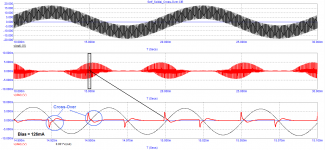
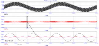
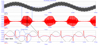
examples of crossover distortion versus quiescent current are shown here:
https://www.diyaudio.com/community/threads/crossover-distortion-the-truth.315698/post-7091133
https://www.diyaudio.com/community/threads/crossover-distortion-the-truth.315698/post-7091133
Regarding the work of negative feedback in audio frequency amplifiers, Kirill Hamer spoke competently in an interview with the magazine.
His statement is confirmed by David Hafler's SWDT test.
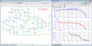
As an example, let's take a typical amplifier repeatedly described in various sources.
His statement is confirmed by David Hafler's SWDT test.
As an example, let's take a typical amplifier repeatedly described in various sources.
Attachments
-
Cyrill Hammer_interview.pdf207.7 KB · Views: 132
-
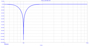
 Self-typical_Bode.png26.7 KB · Views: 138
 -
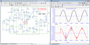
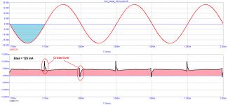 Self-typical_10kHz(-)_Bias=126mA_distortion.png11.6 KB · Views: 136
 -
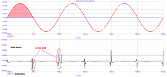
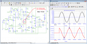
 Self-typical_10kHz(+)_Bias=15mA_distortion.png11.4 KB · Views: 115
 -
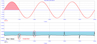
 Self-typical_10kHz(+)_Bias=86mA_distortion.png12 KB · Views: 113
 -
 Self-typical_10kHz(+)_Bias=126mA_distortion.png11.5 KB · Views: 111
 -
 Self-typical_Bias=86mA_Cross-Over.png16.3 KB · Views: 107
 -
 Self-typical_Bias=126mA_Cross-Over.png16.5 KB · Views: 136

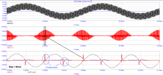
The situation is better with the Darlington "two" output stage at the same quiescent currents. However, due to the relatively large signal propagation delay time, the peak value of high-speed distortion is greater than the level of non-linear distortion.
Attachments

If you want to measure crossover distortion to set your bias, it's pretty simple, especially on a stereo amp:
Use one channel to output a sinewave of large amplitude (like 24V, 20kHz).
Connect it through a big 4-8 ohm power resistor to the output of the channel you want to test, to inject a current into it. It's gonna get hot, so check the watts! Ground the input of the channel under test.
Tada! The output of the amp under test should be 0V, since its input is grounded. The voltage there consists entirely of distortion, plus a little bit of voltage due to the impedance of the output inductor, relays, etc. For a better signal, you can bypass the output inductor. And now you can see your crossover distortion it on a scope in all its glory, without it being hidden by the huge output voltage.
Since the input of the output stage is now at low voltage, nothing stops you from using an instrumentation amplifier to measure the voltage between the input and the output of that output stage. So you can even get your crossover distortion without feedback trying to hide it.
So assuming an SE amp the output connection is amp1+ ---> 8R ---> amp2+, and that's it?If you want to measure crossover distortion to set your bias, it's pretty simple, especially on a stereo amp:
Use one channel to output a sinewave of large amplitude (like 24V, 20kHz).
Connect it through a big 4-8 ohm power resistor to the output of the channel you want to test, to inject a current into it. It's gonna get hot, so check the watts! Ground the input of the channel under test.
Tada! The output of the amp under test should be 0V, since its input is grounded. The voltage there consists entirely of distortion, plus a little bit of voltage due to the impedance of the output inductor, relays, etc. For a better signal, you can bypass the output inductor. And now you can see your crossover distortion it on a scope in all its glory, without it being hidden by the huge output voltage.
Since the input of the output stage is now at low voltage, nothing stops you from using an instrumentation amplifier to measure the voltage between the input and the output of that output stage. So you can even get your crossover distortion without feedback trying to hide it.
Yes single ended amp in stereo (or 7 channel or whatever).SE you mean stereo and not bridged? If so, yes
this method is usually used to measure the output impedance of an amplifier. But if there are no filters to suppress the main signal, then crossover distortion can be estimated in this way.If you want to measure crossover distortion to set your bias, it's pretty simple, especially on a stereo amp:
Use one channel to output a sinewave of large amplitude (like 24V, 20kHz).
Connect it through a big 4-8 ohm power resistor to the output of the channel you want to test, to inject a current into it. It's gonna get hot, so check the watts! Ground the input of the channel under test.
Tada! The output of the amp under test should be 0V, since its input is grounded. The voltage there consists entirely of distortion, plus a little bit of voltage due to the impedance of the output inductor, relays, etc. For a better signal, you can bypass the output inductor. And now you can see your crossover distortion it on a scope in all its glory, without it being hidden by the huge output voltage.
Since the input of the output stage is now at low voltage, nothing stops you from using an instrumentation amplifier to measure the voltage between the input and the output of that output stage. So you can even get your crossover distortion without feedback trying to hide it.
Attachments
Yes, static crossover distortion is just another name for "current-dependent nonlinear output impedance variations"... To nitpick, I would not put the spikes due to transistors that turn off too slowly in the "output impedance" category, but this test will cause them to show up regardless.this method is usually used to measure the output impedance of an amplifier.
CFP/Sziklai is absolutely terrible in this regard, unsuitable for class AB, only for class A
You did an X-Y display, but you should have doen a channel 1 minus channel 2 display.Well, I only got straight 45 deg. line. While increasing input frequency past 10kHz, the line was getting oval shape (phase shift).
jan
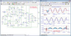
Crossover (switching) distortions appear mainly in class AB amplifiers with global negative feedback having low speed.
The feedback speed depends on the signal transit time (time Propagation Delay), in other words, on the signal arrival delay at the comparison node.
Until now, the main attention has been paid to THD measurements, which are carried out in a steady state and do not reveal many types of really introduced distortions, such as: high-speed distortions, the appearance of a constant component depending on the polarity of the first half-cycle of the signal, and others.
Not all radio amateurs have access to professional measuring equipment. But even with professional equipment today, audio equipment designers first design circuits and test and optimize their parameters in simulators.
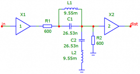
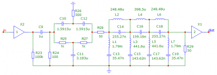
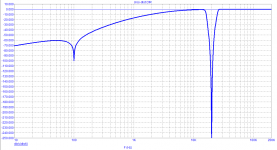
The simplest way to isolate the distortion products of a given frequency is to use notch filters.
Two filters are offered to the attention of radio amateurs.
Transients in a 10 kHz notch filter take about 15 periods (1.5 ms), so when using such a filter, set the test time to 2 ms or more and look at the distortion products after 1.5 ms. In a number of amplifiers, a constant component appears in the products. In such cases, change the polarity of the input signal and test again.
Transients in the 100 Hz and 20 kHz filter take 5 to 10 ms. Therefore, when testing, we set the time to 30 ms and look at the distortion products after 10 ms. If necessary, we stretch the area of interest to us.
The feedback speed depends on the signal transit time (time Propagation Delay), in other words, on the signal arrival delay at the comparison node.
Until now, the main attention has been paid to THD measurements, which are carried out in a steady state and do not reveal many types of really introduced distortions, such as: high-speed distortions, the appearance of a constant component depending on the polarity of the first half-cycle of the signal, and others.
Not all radio amateurs have access to professional measuring equipment. But even with professional equipment today, audio equipment designers first design circuits and test and optimize their parameters in simulators.
The simplest way to isolate the distortion products of a given frequency is to use notch filters.
Two filters are offered to the attention of radio amateurs.
Transients in a 10 kHz notch filter take about 15 periods (1.5 ms), so when using such a filter, set the test time to 2 ms or more and look at the distortion products after 1.5 ms. In a number of amplifiers, a constant component appears in the products. In such cases, change the polarity of the input signal and test again.
Transients in the 100 Hz and 20 kHz filter take 5 to 10 ms. Therefore, when testing, we set the time to 30 ms and look at the distortion products after 10 ms. If necessary, we stretch the area of interest to us.
Attachments
- Home
- Amplifiers
- Solid State
- Measuring crossover distortion / bias