An active notch has the advantage that you can adjust the width (steepness) of the notch, and it does not attenuate the signal.
A passive notch is so wide it attenuates the lower harmonics quite a lot, especially 2. + 3.
But it adds no noise and very little distortion on its own (150dB possible). Samuel Groner used a passive notch with correction tables in his master thesis for this reason I think.
A passive notch is so wide it attenuates the lower harmonics quite a lot, especially 2. + 3.
But it adds no noise and very little distortion on its own (150dB possible). Samuel Groner used a passive notch with correction tables in his master thesis for this reason I think.
Ok, here is one example I just made.
Pioneer SA-540 amplifier was tested, using passive 2kHz twin t-notch filter and my laptop as a sinewave generator (not the best one).
I turned the volume up to a clipping point (50V p-p).
So what we see?
Well, it looks like amplifiers negative side is clipping sooner than positive. There is also some evidence of crossover distortion, but Im not sure if it comes from amplifier or laptop itself? It appeared also when I tested two different amplifiers.
Crossover distortion is not seen at the exact zero cross of sine wave, not sure why.. ?
10V/div for residual and 20mV/div for filtered input.
Last edited:
Check out Nelson Pass's article on the Harman Kardon Citation 12, all you need a scope, signal generator and an 8 Ohm load. I've used several times works great.
Craig
Craig
If you have high order harmonic distortion level is higher than low order harmonic distortion, likely it is from crossover distortion.
You can hear crossover distortion clearly when you set the volume as low as possible but you can still hear the sound. You can hear the high frequency distort. When you set bias to optimum value, you can not hear the crossover distortion, but other distortion still exist.
You can hear crossover distortion clearly when you set the volume as low as possible but you can still hear the sound. You can hear the high frequency distort. When you set bias to optimum value, you can not hear the crossover distortion, but other distortion still exist.
Ok, here is one example I just made.
Pioneer SA-540 amplifier was tested, using passive 2kHz twin t-notch filter and my laptop as a sinewave generator (not the best one).
I turned the volume up to a clipping point (50V p-p).
So what we see?
Well, it looks like amplifiers negative side is clipping sooner than positive. There is also some evidence of crossover distortion, but Im not sure if it comes from amplifier or laptop itself? It appeared also when I tested two different amplifiers.
Crossover distortion is not seen at the exact zero cross of sine wave, not sure why.. ?
10V/div for residual and 20mV/div for filtered input.
View attachment 855694
Germanium and silicon transistors have different switching patterns.
A quasi-complementary output stage is different from a conditionally complementary one. A pair of triple.
Enough to trim the output stage bias for lowest THD.
Trim the output stage bias for your THD taste. 😉
I didn't look all the posts. You can use subtraction method look here post 125
LM1875 in parallel configuration and used in a composite amplifier.
LM1875 in parallel configuration and used in a composite amplifier.
Last edited:
This is what I do .. according to me it works
Use a resistive dummy load does not have to be 8 ohms you may use 28 or 33 ohms ... not critical at all ... but must have one
Feed the input with a triangular wave medium frequency 1kHz will work
Set the level of the signal to have around 5 volts peak to peak at the output of the amplifier
Now with the oscilloscope measure the signal at the output .... if the amplifier works it will look almost perfect
Then with the oscilloscope measure the signal in the VAS stage ... lower side or upper side of the output bias transistor .... if the bias is too low at crossover point you will have a step ... if so increase bias until the step is no more visible .. then you may increase bias a few % more.
And this is it !
There are two fundamental ways to measure / look at distortion that I tried:
1. Compare amp input to divided-down amp output. A classical 3-opamp instrumentation amp with very good opamps and resistors matched to <0.01% will do. Note you need an adjustable first order low pass at the direct input to make up for limited bandwidth of the amp. This is basically a distortion magnifier with magnification of 10.000x and no THD analyser needed. Manual adjustment is a hassle and everything under say 0.01% THD gets buried in noise. But this is the most intuitive method.
For audio frequencies, method 1 is used in industry. An AD8429 will do great here since it is 1nV/rtHz input referred noise at a gain of 1000. Also in industry, getting resistors matched at <0.01% due to budget, but you can always use a pot configured in a way to give you high resolution (one turn is a very small delta R).
Here is my 1 dumb allowed question for the day. What is a REW?
No dumb question.. REW - Room EQ Wizard Room Acoustics Software
Here is my 1 dumb allowed question for the day. What is a REW?
Complete how to guide here:
Howto - Distortion Measurements with REW
Here is the rig:
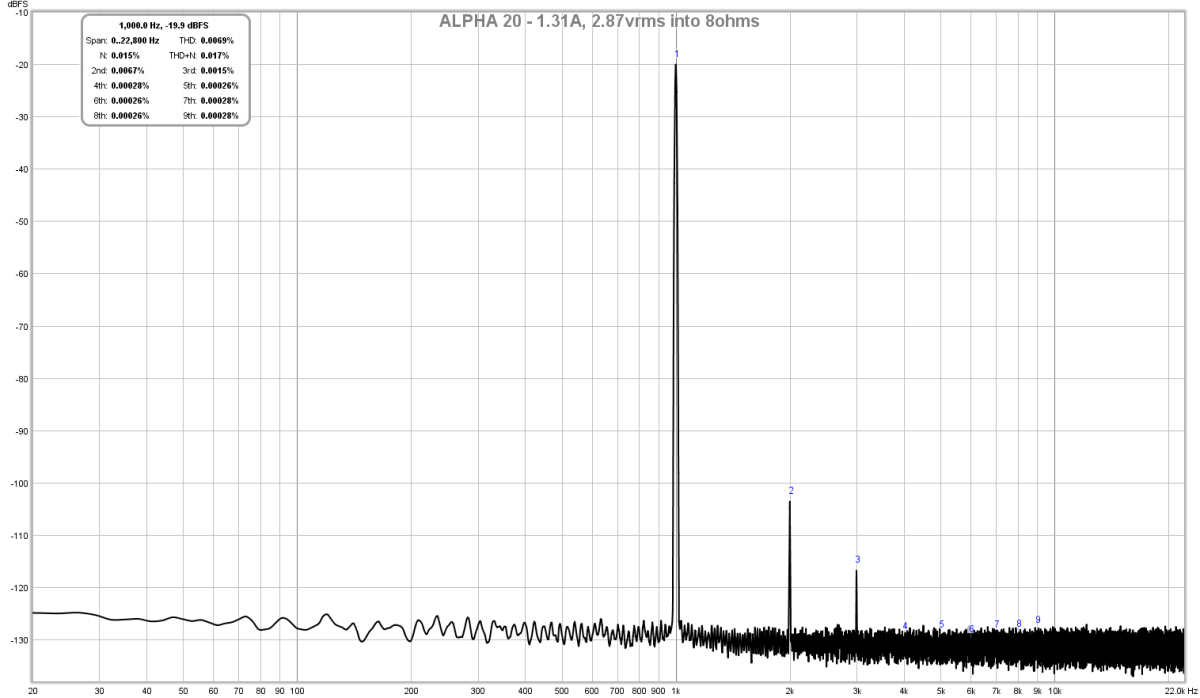
You can get data like this easily with REW:
Last edited:
Complete how to guide here:
Howto - Distortion Measurements with REW
Here is the rig:
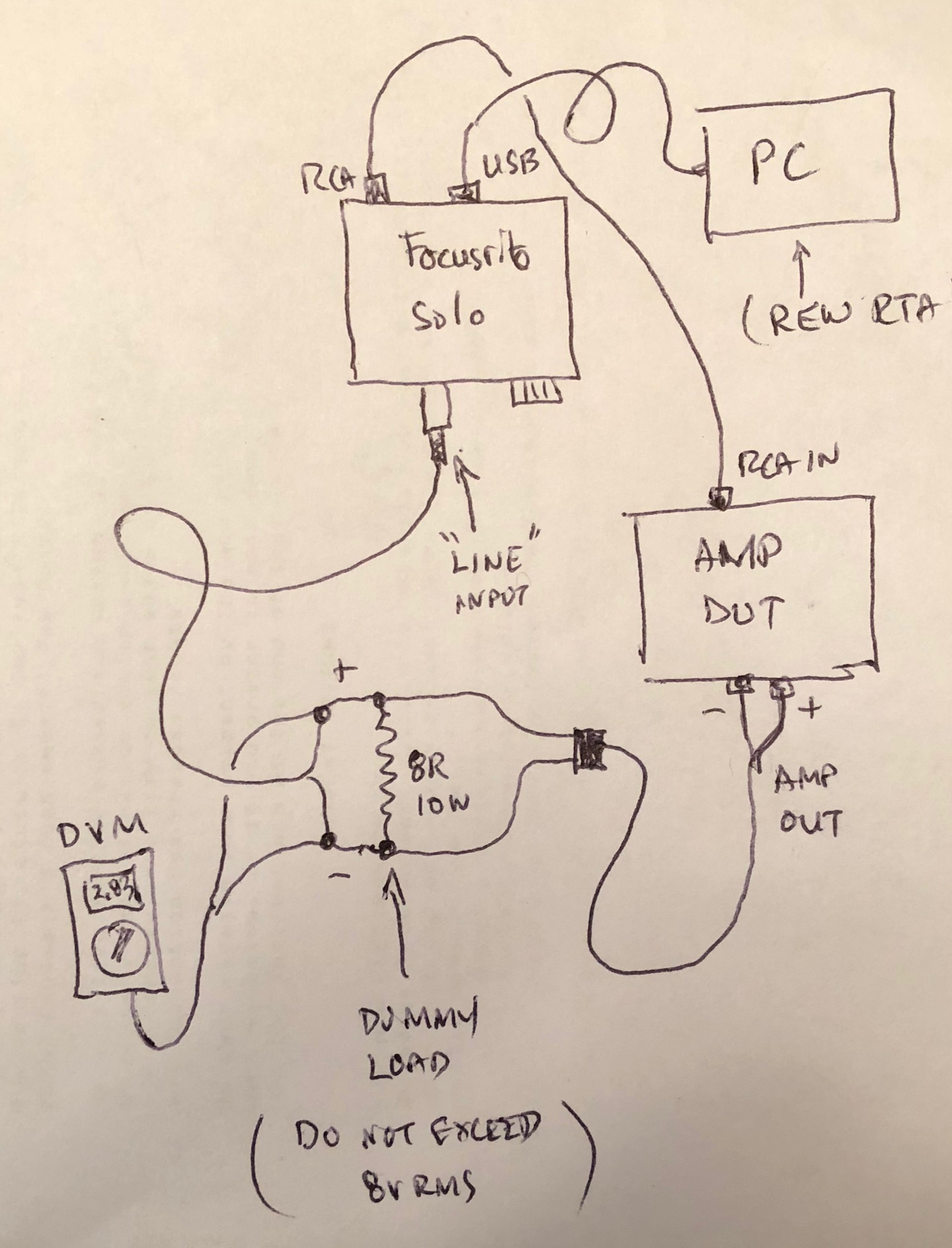
You can get data like this easily with REW:
I understand the value of REW, its a free tool, and a good one, but I never liked it, I always felt something amateur about it. I pretty much prefer a QA401 QuantAsylum interface, dont have to worry about calibration or anything and it can stand a lot more than 8V with the included pad, and its costs a little bit more than a Focusrite sound card.
Last edited:
You just need to add a voltage divider if running higher than the max input preamp voltage on the audio interface. I have measured as high as 90Vpp with a similar setup with a few more resistors.
Not sure what you think looks “amateurish” about REW. It’s quite capable and the graphs look great - better than many “pro” packages, IMO.
Not sure what you think looks “amateurish” about REW. It’s quite capable and the graphs look great - better than many “pro” packages, IMO.
Not sure what you think looks “amateurish” about REW. It’s quite capable and the graphs look great - better than many “pro” packages, IMO.
The thing is that REW is not what it used to be years ago, it started as being an EQ wizard for you to tune or eq your system in a room, then it got many features included and became what it is today.
Managed to fine tune the bias of QSC USA 850 amplifier. It was a little bit low, so that crossover spikes were visible. Also some harmonics can be seen here.
So yes, this simple notch filter works.
But there is some drifting issues, not sure if its my cell phone (signal generator) or something else, but it needs finetuning all the time to get maximum fundamental attenuation.


So yes, this simple notch filter works.
But there is some drifting issues, not sure if its my cell phone (signal generator) or something else, but it needs finetuning all the time to get maximum fundamental attenuation.
- Home
- Amplifiers
- Solid State
- Measuring crossover distortion / bias