That was why I asked, there seemed to be no qualifiers. There's been a lot of work on cone materials and motors since then, though the dimensions are more similar than dissimilar, companies like Dynaudio being an exception. I wouldn't be surprised, though, that the current similarities have as much or more to do with production costs than the actual ideal of dimensions.Please realize this is for normal cone drivers used for as much bandwidth as those might offer. Special needs change requirements like cost or whatever. I also believe the line probably should not be dead straight but then how to bend it?
Dave
The mass of the voice coil assembly has not changed much even though cone material choices are more with the exception that things like SuperNil are gone and like whatever the cone was for the Jack's speakers is unknown except to Jack or the Darnel (sp?) cone material in the flame on factory. So with that mass defined the cone moving mass is defined and the voice coil size to cone size comes out the same.
((((snip))))
In my follow-up question to you (indeed from the start), I especially had in mind the low range and in your case, the octave below 60 where mics, hearing, equal-loudness curves, and preference might part company. I should have said so. Hard to say if the fine-tune-by-ear advocates are thinking of extremes of bass or treble or the whole range. And if treble, where does presbycusis fit in.
I'll do some measurements of the low end with the sub on--how I typically listen unless it's to NPR. I did adjust it by ear b/c I don't have the ability to EQ well. I haven't touched or felt the need to touch the level, crossover or phase in a few weeks, so it's the keeper until I find an EQ that I like. Since the my room is modal from 200Hz down I really need an EQ there for measurements to be useful in a sense--other than for a demo of what I listen to. My bet is that I'd prefer a bit of boost down low as opposed to flat, but it's impossible to do flat right now for me so I can't really know for sure. I only have 2 subs as well so to get really flat on the low end may well be impossible regardless.
Here's an old graph from when I first got the subs just to show where the room goes modal:

Yea, this could sound bass heavy. The graph is from 5 positions across the couch with 1/12 octave smoothing for some sense of clarity about what's happening.
One interesting thing to me is that the big bumps in the low end on that graph do not correlate very well with room dimensions. Then again, the room is essentially "S" shaped and that might be causing my deviation--let alone boundary stiffness. I'd love to see how this room would model with the subs in their present location vs. how it actually graphs.
SUM, that speaker is a stupid cheap Behringer monitor that I did a little mod to to get that response. It's essentially a copy of a Mackie monitor only passive and ported on the baffle. The ports were causing ripples in the off axis response and even somewhat on axis. Here's some pretty pictures from REW V5 beta to show the difference:


from the impulse you can see the first reflection is earlier on the one with cotton in the ports and it contaminates the graph more.
There's a phase flip at the crossover point and near that peak at approx 18kHz. Let me see if I can make a graph real quick.

Dan
Last edited:
There's a phase flip at the crossover point and near that peak at approx 18kHz. Let me see if I can make a graph real quick.
Dan
You do realize that the phase flip is just a property of the plotting routine, and if you had choosen slightly different air path delay the flip points would have moved significantly, right? I only ask because it seems that others are putting some credence to where the flips occur and yet they actually mean nothing.
David
No, I didn't know that Dave. FWIW, I'm not worried about phase. I was just posting it for SUM. Thanks for the information though. I wish I knew exactly what it means.
I do know that at every axis, that flip is slightly different. I'll check out what happens to the upper flip as well. OK, the upper on moves around a bit as well. and is virtually gone from a further mic distance.

Is there a proper way to measure phase from a microphone then?
Thanks again,
Dan
I do know that at every axis, that flip is slightly different. I'll check out what happens to the upper flip as well. OK, the upper on moves around a bit as well. and is virtually gone from a further mic distance.
Is there a proper way to measure phase from a microphone then?
Thanks again,
Dan
Last edited:
No, I didn't know that Dave. FWIW, I'm not worried about phase. I was just posting it for SUM. Thanks for the information though. I wish I knew exactly what it means.
Is there a proper way to measure phase from a microphone then?
Thanks again,
Dan
Whenever we measure a speaker and its phase, there is a given time delay due to the distance that the microphone is from the speaker (1 meter or 2 meters, say). This gives a ton of phase shift that is a function of mic distance rather than any characteristic of the speaker, so most programs let you define the "air path delay" and the program compensates for that.
Since the distance from the microphone to the speaker is usually a little approximate (To the baffle? To the acoustic center? To the tweeter voice coil?) the exact amount of phase shift that is "unwrapped" will be similarly approximate. (Some advocate matching the phase to the Hilbert transform of the tweeter, not something I would lose sleep over.)
Think of phase measurements as comparing two sine waves. If wave A is 1/4 cycle ahead of wave B then we could say it has 90 degrees lead. But it could just as well be 270 degrees lag or 630 degrees lag. (270 + 360). We never know, because these ideal sign waves go on forever and started long ago. One cycle looks the same as the next. The plotting routines are the same. If they plot over a +-180 degree range, then whenever the curve gets to one edge it flips to the opposite edge and continues.
Set the air path delay to the distance from mic to baffle and feel free to adjust a little if it reduces the number of phase flips or makes the graph clearer. The location (or number) of flip points means nothing.
David
Last edited:
You do realize that the phase flip is just a property of the plotting routine...
I'd really like to see amplitude & phase plotted as a curve on rotatable 3D plot. It would then be easier to get a solid feel for the data.
Here is an example from Heyser of the plot, and what collapes out when you look into a couple different axes.
dave
Attachments
David, you are a valuable resource around here! Very clear and detailed though I don't honestly know what the Hilbert transform is. Doesn't matter to me right now. The more I learn the more ignorant I am. Thank goodness you started posting here.
Thanks for the tidbits! I now know how to use more of REW thanks to you. That rhymed.
Dan🙂
Thanks for the tidbits! I now know how to use more of REW thanks to you. That rhymed.
Dan🙂
Last edited:
Small ports are evil and therefore should always be blocked.
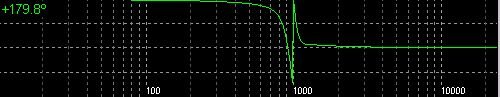
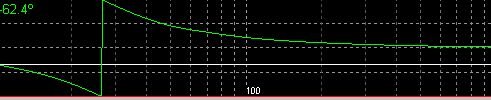
That "phase wrapping" is not really a flip. Flips look kind of like that except the phase will be near zero (if good) and then quite suddenly change to inverted as example. First is a flip and second is a wrapping. Notice on the flip the change is from +180 to 0 quite suddenly. Mode change in a cone will do this. In wrapping simply imagine the line continuing smoothly. Guess which one messes up the sound a whole lot more? 🙂
That "phase wrapping" is not really a flip. Flips look kind of like that except the phase will be near zero (if good) and then quite suddenly change to inverted as example. First is a flip and second is a wrapping. Notice on the flip the change is from +180 to 0 quite suddenly. Mode change in a cone will do this. In wrapping simply imagine the line continuing smoothly. Guess which one messes up the sound a whole lot more? 🙂
Attachments
Last edited:
So you're really saying that the reference is related directly to cone mass, not cone diameter and as stated previously that this is "for normal cone drivers used for as much bandwidth as those might offer". That gives it more credence, though narrow, given the advancements made to date drivers such as the metal cones of Seas and others. It's validity in today's market makes the analysis a lot less applicable, except possibly for those "normal cone drivers", whatever one considers that today. For Seas, a normal cone is more and more often magnesium or Nextel. The former one (pardon the pun) is more their stock in trade today I'd say.The mass of the voice coil assembly has not changed much even though cone material choices are more with the exception that things like SuperNil are gone and like whatever the cone was for the Jack's speakers is unknown except to Jack or the Darnel (sp?) cone material in the flame on factory. So with that mass defined the cone moving mass is defined and the voice coil size to cone size comes out the same.
Compare their ER18 reed-paper, 8.8g for 90db sensitivity to their CA18 classical coated paper, 14g for 88.5db. The suggested usages are 35-2500Hz vs. 45-3000. Each driver's Q is targeted differently, one closed box vs. ported for the other with correspondingly different voice coil lengths. Air gap height is equal, but specified linear travel is 20% more for the latter driver with it's longer coil. Outside of the linear travel, these two are surprisingly close for usage, yet their moving masses differ significantly, 8.8 vs. 14. That's either 37% or 59% depending on the reference.
But if you examine most manufacturer lines, there's usually a commonality of any particular part. Mix-n-match so-to-speak. Market niches are filled. I doubt that either one of those drivers necessarily fits the case of ideal voice coil size, at least one must not since there's such a large disparity in mass if that's the metric. The differing coil lengths coupled with significantly different magnets (Bl 5.6 vs. 7.2) have their effects, but the ratios of mass to Bl aren't a good indicator, either (1.57 vs. 1.94).
Both have the same piston area, 136mm^2. Both would fit the criteria if it is tied to diameter and upper extension only. That still leaves a lot of other drivers out there that don't satisfy either one. It just seems to be a rule-of-thumb that has lost its importance over time. There weren't any magnesium and few other hard cone drivers back then and the market niches are somewhat different today, I'd say. A lot more choices, even for a simple 2-way.
It just doesn't seem very relevant today.
Dave
Last edited:
dantheman- Would you have a simple soft dome tweeter with no lens you could test? One like this or looks like this- Dayton DC28F-8 1-1/8" Silk Dome Tweeter | Parts-Express.com Any brand will do. Would like to see the phase and impulse from one of these type for reference. All these type flip phase at a frequency proportional to the dome size except the Allison- don't use that one. Dynaudio, Audax, Vifa, Peerless, etc.
This would really help me with a point of reference. And because I know every one of this type tweeter flips phase when it changes mode this will show the accuracy of the phase plot.
Thanks a bunch-
Yes- the one on the left- very bad for image and clarity.
DLR- the propagation velocity through the cone and the voice coil is a lot different in paper process cones. If the cone and coil have a similar propagation velocity then as you say "It don't apply" and therefore you are correct. If propagation velocity is nearly the same then termination of the cone at the surround becomes the main concern. Center phase plugs and so on do not change the propagation velocity through the cone. I was wrong to not mention the criteria that the velocity though the voice coil and cone would be significantly different for this to apply. I only use paper process cones and was thinking in a rut.
Maybe I will check out those drivers you mentioned.
Last edited:
Would like to see the phase and impulse from one of these type for reference. All these type flip phase at a frequency proportional to the dome size except the Allison- don't use that one. Dynaudio, Audax, Vifa, Peerless, etc.
This would really help me with a point of reference. And because I know every one of this type tweeter flips phase when it changes mode this will show the accuracy of the phase plot.
I understand your distinction between phase wrap and flip, but you need to explain about flipping with "changing mode".
By flipping I think you mean the large glitch in phase seen when response goes through a deep cancelation notch. I agree it has nothing to do with plotting routines "wrapping" when one phase limit or the other is reached, but I have never seen phase flips or glitches that corresponded with dome size or with modes that didn't cause strong cancellation.
David
re #1444 & phase measurement
Slight topic swerve.
In these forums and elsewhere, mention is made of a Vance Dickason demonstration at an ALMA event, showing that certain measurement systems, are measuring phase inaccurately. Do any of you have the results.
TIA.
Iain.
Slight topic swerve.
In these forums and elsewhere, mention is made of a Vance Dickason demonstration at an ALMA event, showing that certain measurement systems, are measuring phase inaccurately. Do any of you have the results.
TIA.
Iain.
Think I will write Vance and see if he has that.
Somewhere, obviously misfiled, is a wonderful article which shows this using laser interferometry kind of like the Kipple test jig. Cannot find it, @#$&.
No null is required because what happens is the energy is still radiated however more radiation lobes appear. The typical 1" dome will flip near 5400 Hz. You will see a slight rise and then dip and back and then back to flat. Looked for a manufacturer data sheet but all are so smoothed or the points so far apart the the ripple in the response and impedance curves are marketing smoothed away, sorry.
For cone decoupling- "Analysis of Decoupled-Cone Loudspeakers" by James M kates JAES Volume 25, Number 1/2 Jan/Feb 1977 explains the decoupling which is done now days with a curved cone woofers. The is essentially an explanation of how smooth response can be made with a driver which behaves in two different modes.
The typical 1" dome will flip near 5400 Hz. You will see a slight rise and then dip and back and then back to flat. Looked for a manufacturer data sheet but all are so smoothed or the points so far apart the the ripple in the response and impedance curves are marketing smoothed away, sorry.
Flip what? Are you talking about a feature in the phase curve?
All drivers operate for much of their range in a variety of vibrational modes. Some of them have signitures in the frequency response and others are invisible. Certainly, for modes that don't show in the response there are no phase related anomalies.
David
Hello David,
i would expect every mode change to be visible
in the impedance plot - if spreaded wide enough - and
in the frequency response as well.
Since a mode change goes hand in hand with a change in
driving point impedance - bending wave transducer slang -
there has to be a change in phase too.
The question is how severe those changes are. With sufficient
damping modes can blend quite well ...
Have never seen a no lens 1 inch soft dome tweeter (as described earlier post) which does not invert phase on the axis output near 5400Hz. Radiation pattern changes from almost all the energy in a single main lobe to energy in a main lobe on axis and a side lobe (doughnut like around the central lobe of opposite phase). In graphs with fine resolution this may be seen on impedance and frequency response curves. The two lobes are 180 degrees apart in phase. The on axis lobe becomes negative the phase it was below 5400Hz and the side lobe is in the same phase as the main lobe was below 5400Hz.
Last edited:
I use that mono amp with the driver in the feedback loop for the midrange
Are there any links on the "feedback loop" topic?
- Status
- Not open for further replies.
- Home
- Loudspeakers
- Multi-Way
- Measurements: When, What, How, Why