The scale is just like that. The resistive part is a bit different, but normally when we do XO analysis, no software distinguishes the difference between these two in terms of the impedance phase even though both are labeled the same unductance value. Surely this will effect speaker response.Check your imp. mag. scale. Should be log for starters. You should see the lower one being resistive instead of inductive at low f.
The scale is just like that. The resistive part is a bit different, but normally when we do XO analysis, no software distinguishes the difference between these two in terms of the impedance phase even though both are labeled the same unductance value. Surely this will effect speaker response.
Well, try changing the scale so that it´s from 0 to 10 ohms. You should see what I mean...
If you look at the impulse response I posted, there is a huge reflection, almost as big as the direct sound. Add that to numerous smaller reflections that go on for a long time and you're almost certainly going to have non-minimum phase behavior. Gate to 8 ms and the behavior looks more like minimum phase below 3K in the excess phase and excess group delay plots. There's still some weirdness above 3K but the excess group delay only spikes up to 9 ms or so. If I don't gate it, I get excess group delay similar to John's (with different software).The context was "here is a driver and its measurements". The discussion then became whether it (the driver) was minimum phase or not. If the measuring environment was leading to a conclusion that the driver wasn't minimum phase, then I would consider that misleading. I still maintain, and it seems Earl agrees, that the spikes are as likely an artifact of the differentiation process. They certainly aren't characteristic of the driver.
http://www.diyaudio.com/forums/multi-way/166411-measurements-when-what-how-why-112.html#post2241613
I hope that helps clarify excess group delay somewhat, though having read through some of the postings in this thread learning from one another does not appear to be high on the agenda.
It's a forum.
Probably the better approach is creating an article on the forum consolidating this information, then requesting feedback and editing the article "on the fly". (..then placing the article's link in your signature line for the forum.)
If you look at the impulse response I posted, there is a huge reflection, almost as big as the direct sound. Add that to numerous smaller reflections that go on for a long time and you're almost certainly going to have non-minimum phase behavior. Gate to 8 ms and the behavior looks more like minimum phase below 3K in the excess phase and excess group delay plots. There's still some weirdness above 3K but the excess group delay only spikes up to 9 ms or so. If I don't gate it, I get excess group delay similar to John's (with different software).
http://www.diyaudio.com/forums/multi-way/166411-measurements-when-what-how-why-112.html#post2241613
If gating in large part cleans it up then "excess group delay spikes" are an attribute of the room. There was never a question that the in-room response wold be non MP. The initial discussion was about whether the driver was MP or not and also whether roughness in the phase curve was of significance.
If we want to characterize the driver we need to get as anechoic a measurement as possible, and further must discount measurement artifacts that may be residual room effects.
David S
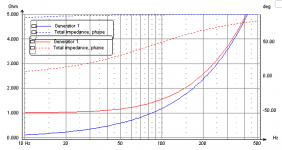
The XO software should calculate the phase correctly. This is from LspCAD simulating a 1.9 mH inductor with (almost) 0 DCR and with 1 ohm DCR. That said, I'd expect your top graph to show more phase droop down low so I don't know what's going on there.The scale is just like that. The resistive part is a bit different, but normally when we do XO analysis, no software distinguishes the difference between these two in terms of the impedance phase even though both are labeled the same unductance value. Surely this will effect speaker response.
Attachments
If you look back they are not all near 150ms, but artefacts are certainly likely in measurements with deep notches - phase changes from -90 to +90 on passing through (or close to) a zero in the response, which causes ambiguities in phase unwrapping as it becomes difficult (or impossible) to determine whether a large positive phase change between samples is due to a phase wrap or a zero. Getting that decision wrong typically results in sharp negative spikes in group delay close to (likely genuine) positive spikes. Even in the absence of notches, room effects can result in measured phase gaining a cycle of lag over quite a small frequency span, with nothing in the amplitude response (and hence nothing in the minimum phase response) to suggest why. Near field, suitably gated or anechoic measurements make life much easier, of course.I'd still lay money that a number of delay spikes all near 150ms, is a computational artifact. What would you attribute it to?
I see. Never thought that little bit of resistance (0.5ohm in my case) would make that much difference in the phase. But has anyone measured how this difference would effect the low frequency response. Since the impedance phase has so much variation, there should be some measurable and audible difference.The XO software should calculate the phase correctly. This is from LspCAD simulating a 1.9 mH inductor with (almost) 0 DCR and with 1 ohm DCR. That said, I'd expect your top graph to show more phase droop down low so I don't know what's going on there.

I see. Never thought that little bit of resistance (0.5ohm in my case) would make that much difference in the phase. But has anyone measured how this difference would effect the low frequency response. Since the impedance phase has so much variation, there should be some measurable and audible difference.
The phase angle is between the resistive part and the reactive part. 45 deg would mean equal magnitudes ie. 1 ohm resistance, 1 ohm reactance. Easy to calculate.
I see. Never thought that little bit of resistance (0.5ohm in my case) would make that much difference in the phase. But has anyone measured how this difference would effect the low frequency response. Since the impedance phase has so much variation, there should be some measurable and audible difference.
Yes. The series resistance of the inductor needs to be added into the passive crossover design. The resistance causes loss and the "apparent" load is higher so the coil needs to be larger obviously. The change is phase should show up in the model with the driver. All these factors do pretty much exactly what one would expect. Higher Q in the sealed box, lower sensitivity of the driver, less control over driver motion because of the resistor in series with the low output impedance amplifier, more dynamic compression because of the lack of control and so on.
Know what is informative and very easy? Take any driver that will produce some midrange like a 6 or 8 inch or so and hook it up directly to an amplifier box or not. Next place a .27 ohm or so resistor in series with that same setup and listen. Doing this will make you want to never use a passive crossover again.
🙂=SUM
I see. Never thought that little bit of resistance (0.5ohm in my case) would make that much difference in the phase. But has anyone measured how this difference would effect the low frequency response. Since the impedance phase has so much variation, there should be some measurable and audible difference.
Only inductors in series with the woofer are much of an issue. In the upper range this resistance just becomes part of the Q of the resonance. But the series resistance of the woofer series inductors needs to be accounted for. In a closed box the difference is negligable, in a ported, more of a concern. But in neither case is it something that cannot be designed for.
In tube amps the output resistance is much higher than the series resistances of inductors. That doesn't seem to be such an issue with them, even though it can cause very large changes in frequency response of the crossover.
There's nothing wrong with passive crossovers as long as the response of the driver + filter meets your acoustic target response. Some would say that a good passive crossover does 'less harm' than a bunch of opamps or an AD-DSP-DA solution. Me, I'm agnostic on the subject. Both can be done well and both can be done poorly.Know what is informative and very easy? Take any driver that will produce some midrange like a 6 or 8 inch or so and hook it up directly to an amplifier box or not. Next place a .27 ohm or so resistor in series with that same setup and listen. Doing this will make you want to never use a passive crossover again.
my series resistance experiment with an OB sub some time last year:
"I added 9.2 Ohms of series resistance to my OB sub, a Hawthorne 15" Augie. I was basically trying to see what the Carver Amazing Loudspeaker might have sounded like and squeeze more deep bass out of the Augie. There was a suitable resistor (e.g. 9.2 Ohm 1% 50 watt) available at a local surplus supplier HSC Electronic Supply - Silicon Valley's Electronic Marketplace for $1.75/ea, so I decided to give-er-a-go. Fancier circuits could have been and still can be implemented that waste less power, but this was quick and easy.
My baffle is 2 ft tall by 3 ft wide which is larger than most anyone uses with an Augie and considered more than optimal by most Augie users. I just had not bothered to cut the board I bought for the purpose of baffling the Augie b/c it used to fit so well under the TV. The theory of operation here at HA, which is not new and has been used "for many long years I know"(for Blues fans), is that you can use a thinner baffle than what would be calculated to mount a highish Q woofer b/c the added bass boost at resonance will compensate for the roll-off caused by the the baffle width. The 2 responses will combine and make a nice, smooth, extended bass response to somewhere near driver resonance. From my limited understanding it seems reasonable enough. So the Solo/Duet is 24" wide and the Amazing Loudspeaker, from what I can find on the web, is 30" wide at the bass but thinner at the top. Not all that different but the frequency extension of the Solos is usually measured somewhere between the mid 40s to 50s by the users capable of doing so while the Amazing supposedly does 20Hz (though I haven't seen that measured anywhere). I don't recall anyone stating how deep the Augies went in their rooms. I know from experience that it sounds deeper then the PSI by itself.
The Qts of the Amazing woofer according to many sources on the Web is around 3, the PSI and Augie are more near a normal 0.9. The resonance of the Augie is 27Hz where as the Amazing woofer is usually stated as 22Hz. The equation for adjusting woofer Q with series resistance according to True Audio: Audio Spectrum Analyzer and Loudspeaker Design Software is given as Q(tc) = Q(tco) ( (Re + Rg)/ Re ). The relevant Augie specs are given as Re: 5.69 Ohms and Qt: 0.92. Plugging the numbers into the equation with the 9.2Ohm resistors gives us Q(tc)= 0.92 ((5.69+9.2)/5.69). Our new Q(tc) is then 2.4 if I did my math correctly. That's close enough to the Amazing IMO to see what the effect may be and my additional baffle width will maybe compensate for my lower Q(tc). Of course my Resonant Frequency is also 5Hz higher, but I just don't feel like cutting my baffle today .... This also means that I have virtually no DF, but prior experience has left me unconvinced of it's worth anyway. YMMV
I have no measuring equipment, but listening impressions basically go like this: Augie w/o resistor is putting out a lot more midrange, but apparently less deep bass. As far as bass quality goes (the usual fast vs. slow bass argument) I can't tell the difference. YMMV on that one as well. Many people claim to hear the effect, but I discovered today that I really cannot. At least not easily. Sort of a bummer. I was always hoping for the magic Q(tc) of 0.5 to cure all that ales my bass. Just yesterday I thought that the quality of bass was mostly determined by Q(tc). Now I don't know what to think. I mean I also thought that OB bass was less affected by the room than boxed bass. Perhaps this is untrue as well? If there isn't any perceivable difference in quality, might the room and room modes still have a profound effect on the bass we get from OB? I don't know, just thinking out loud. There are a lot of factors that could be at play here. B_Y3P!
Just a note on the set-up: I've got a 24 db/octave LR x-over set just below 60Hz, a 250 watt amp driving the Augie and 25 watt amp on the PSI.
Here are some computer simulations of the 2 different responses courtesy of Scorpion from Audio Circle:
withought added resistance

with 9.2Ohm resistance

U Baffle

As far as I know these don't take the room into consideration though. With the decreased efficiency I have bottomed the Augie out for the first time during an explosion on a movie but apparently did no damage."
Dan
"I added 9.2 Ohms of series resistance to my OB sub, a Hawthorne 15" Augie. I was basically trying to see what the Carver Amazing Loudspeaker might have sounded like and squeeze more deep bass out of the Augie. There was a suitable resistor (e.g. 9.2 Ohm 1% 50 watt) available at a local surplus supplier HSC Electronic Supply - Silicon Valley's Electronic Marketplace for $1.75/ea, so I decided to give-er-a-go. Fancier circuits could have been and still can be implemented that waste less power, but this was quick and easy.
My baffle is 2 ft tall by 3 ft wide which is larger than most anyone uses with an Augie and considered more than optimal by most Augie users. I just had not bothered to cut the board I bought for the purpose of baffling the Augie b/c it used to fit so well under the TV. The theory of operation here at HA, which is not new and has been used "for many long years I know"(for Blues fans), is that you can use a thinner baffle than what would be calculated to mount a highish Q woofer b/c the added bass boost at resonance will compensate for the roll-off caused by the the baffle width. The 2 responses will combine and make a nice, smooth, extended bass response to somewhere near driver resonance. From my limited understanding it seems reasonable enough. So the Solo/Duet is 24" wide and the Amazing Loudspeaker, from what I can find on the web, is 30" wide at the bass but thinner at the top. Not all that different but the frequency extension of the Solos is usually measured somewhere between the mid 40s to 50s by the users capable of doing so while the Amazing supposedly does 20Hz (though I haven't seen that measured anywhere). I don't recall anyone stating how deep the Augies went in their rooms. I know from experience that it sounds deeper then the PSI by itself.
The Qts of the Amazing woofer according to many sources on the Web is around 3, the PSI and Augie are more near a normal 0.9. The resonance of the Augie is 27Hz where as the Amazing woofer is usually stated as 22Hz. The equation for adjusting woofer Q with series resistance according to True Audio: Audio Spectrum Analyzer and Loudspeaker Design Software is given as Q(tc) = Q(tco) ( (Re + Rg)/ Re ). The relevant Augie specs are given as Re: 5.69 Ohms and Qt: 0.92. Plugging the numbers into the equation with the 9.2Ohm resistors gives us Q(tc)= 0.92 ((5.69+9.2)/5.69). Our new Q(tc) is then 2.4 if I did my math correctly. That's close enough to the Amazing IMO to see what the effect may be and my additional baffle width will maybe compensate for my lower Q(tc). Of course my Resonant Frequency is also 5Hz higher, but I just don't feel like cutting my baffle today .... This also means that I have virtually no DF, but prior experience has left me unconvinced of it's worth anyway. YMMV
I have no measuring equipment, but listening impressions basically go like this: Augie w/o resistor is putting out a lot more midrange, but apparently less deep bass. As far as bass quality goes (the usual fast vs. slow bass argument) I can't tell the difference. YMMV on that one as well. Many people claim to hear the effect, but I discovered today that I really cannot. At least not easily. Sort of a bummer. I was always hoping for the magic Q(tc) of 0.5 to cure all that ales my bass. Just yesterday I thought that the quality of bass was mostly determined by Q(tc). Now I don't know what to think. I mean I also thought that OB bass was less affected by the room than boxed bass. Perhaps this is untrue as well? If there isn't any perceivable difference in quality, might the room and room modes still have a profound effect on the bass we get from OB? I don't know, just thinking out loud. There are a lot of factors that could be at play here. B_Y3P!
Just a note on the set-up: I've got a 24 db/octave LR x-over set just below 60Hz, a 250 watt amp driving the Augie and 25 watt amp on the PSI.
Here are some computer simulations of the 2 different responses courtesy of Scorpion from Audio Circle:
withought added resistance
with 9.2Ohm resistance
U Baffle
As far as I know these don't take the room into consideration though. With the decreased efficiency I have bottomed the Augie out for the first time during an explosion on a movie but apparently did no damage."
Dan
There's nothing wrong with passive crossovers as long as the response of the driver + filter meets your acoustic target response. ... Both can be done well and both can be done poorly.
I could not agree more. having done both very ofetn, all I ever found was that they sounded the same (when done right of course) but the active was always more expensive. Whats the point!?
Whats the point!?
It's a lot easier just dropping an active crossover into the mix. Especially a Digital one where you have delay, EQ and so on. Sure it's more expensive but taking the time to learn how to do passives and getting good simulation software isn't cheap either.
Rob🙂
Yes, I should have noted the different perspectives - it makes all the difference. Active is easy to do and when ease of implimentation is an important factor it makes perfect sense. My perspective is different and the cost becomes the overriding consideration. I have all the means necessary to to do any level of passive network complexity with just as much ease as you might with active.
I could not agree more. having done both very ofetn, all I ever found was that they sounded the same (when done right of course) but the active was always more expensive. Whats the point!?
We can find a DCX for under $200. My latest XO costs are around $300 for 3 speakers. With the DCX I can test/listen 8 different XO slopes in an afternoon. That can not be done with any passive design. Prototyping has never been easier and for a DIYer that builds a set of speakers each year for fun the cost of active is FAR CHEAPER then passive!! Amps expensives? Nah, just find a used Panasonic SRX55 with 6 channels of amplification for $50 😉
On the other end of the spectrum, The DEQX is an amazing product. The DEQX may cost a bit of money but if people are spending $10K - $100K or more on speakers alone then that DEQX becomes a value component with its ability to correct all phase issues and allow us to have brickwall filters.
There are so many inherent issues with passive designs like one amp driving driving the design (one amp per driver is better), impedance issues, tolerance of the cap/inductors, etc to phase issues or lost energy in the form of heat that it just makes sense that active is the future.
Last edited:
.... it just makes sense that active is the future.
Self powered maybe, not necessarily active...
My numbers are quite different. And then there are the amps - you forgot about those.We can find a DCX for under $200. My latest XO costs are around $300 for 3 speakers. ... That can not be done with any passive design. Prototyping has never been easier...
Prototyping sure, but thats done once. It all depends on the situation.
There are so many inherent issues with passive designs like one amp driving driving the design (one amp per driver is better), impedance issues, tolerance of the cap/inductors, etc to phase issues or lost energy in the form of heat that it just makes sense that active is the future.
Sorry, but I don't agree with any of this. Why is "one amp per driver" better? Tolerances are all under control. "phase issues"? None of my speakers have melted.
Self powered maybe, not necessarily active...
Self powered? Talk about heat. And reliability! The speakers vibrating the components to failure. I stopped using active powering because of the high failure rate.
- Status
- Not open for further replies.
- Home
- Loudspeakers
- Multi-Way
- Measurements: When, What, How, Why