Heh, that would mean that any driver used out of it's piston mode range, wouldn't it.😉... Most drivers are real &*#% when it comes to phase response. Curved cone woofers are pure sin.
=SUM🙂
Gee, why didn't I think of that? Now there's a novel idea. It doesn't address the point related to baffle diffraction. But thanks for that gem, I do so appreciate it.I have explained that already:
Take for example SoundEasy as you have mentioned. You have to gate out the nearby reflections to obtain the level of minimum phase data usable for system design work driver model data.
Not I. You haven't seen my mic setup.To take the issue further, most people will use a short mic such as an ECM2000 and clamp it to a stand like using a normal mic.
Please tell me what this has to do with unavoidable diffraction not related to improper measurement techniques? That is what we were discussing or at least I was and that the resultant measurements are M-P. I usually approach discussions from the perspective that the measurements made are done appropriately, in this case the only diffraction being that of the baffle and/or nearby drivers.However, the clamp itself will generate some reflection/diffraction, do you gate it out or not? In most cases, the data is sufficient for work even if you don't gate it out, and you can still "consider" the data as "minimum phase" data.
You have yet to actually directly address the point. I'll try once more.
To keep you happy, let's assume that the measurement is made appropriately and any extraneous diffraction is windowed out. Accept or refute with arguments, please. I'm just looking for your position on this, clear and concise.Any time that you measure with SoundEasy and create a driver model to match the measured phase (if you've ever done that, try it if not), the result is the M-P of the response including all diffraction with some specified amount of excess-phase.
Dave
Last edited:
It CAN have reflection and diffraction, just to what extend these reflections and diffraction will polute the data enought that you cannot get data usable for your purpose. Is this not correct? If not, please explain why.
BTW, I only respond like that when people start pointing fingers instead of keeping the discussion subject related. If you can point to the specific post which this is not the case, I will openly appologize.
I'm not clear on what "polute" the data means. You said that a SISO measurement cannot include diffractions and reflections, but it can. To what extent these "polute" the data or do not is open to interpretation.
George, you make very bold claims and then when questioned or refuted you get defensive. Then you tend to backtrack, change your argument and take a "you don't understand" stance. This is all very Asian IMO, to "save face" in a discussion - never admit you were wrong, just change the argument.
The next step is obvious, so I'll head it off - yep, I do make bold claims as well. I will support all that I say to anyone who is polite, but I won't deal with impolite people. I left this thread for quite awhile because of the rudeness of some of its participants. Your generally not rude, and I appreciate that, but you are often incorrect and being defensive doesn't help to learn.
The argument seems to be whether speakers are minimum phase or not, and how to determine it. At least this what I understand anyway, I may be wrong.Gee, why didn't I think of that? Now there's a novel idea. It doesn't address the point related to baffle diffraction. But thanks for that gem, I do so appreciate it.
Not I. You haven't seen my mic setup.
Please tell me what this has to do with unavoidable diffraction not related to improper measurement techniques? That is what we were discussing or at least I was and that the resultant measurements are M-P. I usually approach discussions from the perspective that the measurements made are done appropriately, in this case the only diffraction being that of the baffle and/or nearby drivers.
You have yet to actually directly address the point. I'll try once more.
To keep you happy, let's assume that the measurement is made appropriately and any extraneous diffraction is windowed out. Accept or refute with arguments, please. I'm just looking for your position on this, clear and concise.
Dave
What I'm saying is that for most design cases, it's not necessary to gate out the diffraction/reflection if the magnitude of these are not such that it will influence design judgement, and the measured data can be considered minimum phase even though it is not exactly such.
Please point out where I said "SISO measurement cannot include diffractions and reflections". What I said was minimum phase can only be considered between a single input to a single output.I'm not clear on what "polute" the data means. You said that a SISO measurement cannot include diffractions and reflections, but it can. To what extent these "polute" the data or do not is open to interpretation.
George, you make very bold claims and then when questioned or refuted you get defensive. Then you tend to backtrack, change your argument and take a "you don't understand" stance. This is all very Asian IMO, to "save face" in a discussion - never admit you were wrong, just change the argument.
The next step is obvious, so I'll head it off - yep, I do make bold claims as well. I will support all that I say to anyone who is polite, but I won't deal with impolite people. I left this thread for quite awhile because of the rudeness of some of its participants. Your generally not rude, and I appreciate that, but you are often incorrect and being defensive doesn't help to learn.
My mistake on the spelling "pollute" instead of "polute". What I mean by polluted data is that the measured output containing some form of noise, which can be caused by diffraction, reflection, or just electronics noise.
Please also point out where I changed my argument and qoute them please. I think once we can do that, things will get clearer. Many times I have been accused of doing things like that, and when I ask specifically where and when in the thread it occurs, nobody point's it out. So what does this mean? Probably my English is not so good that people are drawing conclusions of what i post different than what I actually said?
Oh, I do admit it when I find myslf wrong and someone else is right, and I can even quote a few even if you want me to.
Last edited:
George, I'm not going to hunt down all that data, its just a friendly comment to perhaps avoid more conflict.
OK about MP and SISO, maybe I "misunderstood". It sounded to me like you were saying that SISO "could not" contain diffraction and reflections but you meant that it "should not". That it "could not" is incorrect, sounds like we agree on that, that it "should not" is, as I said before, open to interpretation. I include some and I gate some. Maybe thats where the "art" is?
Looks like we are the only two "still up", I guess because we are both in China.
Dan I think you have it. A near field monitor really wants the main lobe of radiation to not point down because it bounces of the console and really messes the sound. This means the main lobe needs to be a little "higher" as in line more with the tweeter than the midrange and maybe even point up slightly. This is not perfect but placement of near field monitor is usually right over the meter bridge or on a table or something less that ideal. Your results cause me to wonder if it was designed sitting on a table or over a meter bridge? Interesting thought. Doubt we will ever know. Mine are...
🙂🙂=SUM
Looks/sounds about right.
Thanks,
Dan
We're in the same time zone. I'm back in Taiwan. Was in the Shanhai area earlier to visit the World Fair, some friends and relatives. It was my son's first time in China, and my second.George, I'm not going to hunt down all that data, its just a friendly comment to perhaps avoid more conflict.
OK about MP and SISO, maybe I "misunderstood". It sounded to me like you were saying that SISO "could not" contain diffraction and reflections but you meant that it "should not". That it "could not" is incorrect, sounds like we agree on that, that it "should not" is, as I said before, open to interpretation. I include some and I gate some. Maybe thats where the "art" is?
Looks like we are the only two "still up", I guess because we are both in China.
Yes, there are so many tradeoffs in design work that it is an art how you pick a choose. That's probably where the fun is.
Re: the minimum phase (MP) stuff people are talking about.
I'm trying to get my head around the MP / non-MP distinction and what it means for audio measurements with loudspeakers and rooms.
I've done the usual 'net searches (including Wikipedia) and they all get into high level maths really early in their explanations.
Does anyone have a straightforward physics/acoustics explanation for what MP means and how non-MP is different from it, that doesn't start talking about "zero poles in the unit circle"?
I suppose the teaching analogy would be like explaining some of Newton's laws using billiard balls on the snooker table rather than just showing the differential equations and saying "so there".😎
Any links or pithy text would be appreciated.
My position, and others will disagree, is that the concept isn't really worth worrying about because it really does not have much impact on anything to do with loudspeakers. EE's worry about it from several different perspectives, but not so much in audio. In simplistic terms it relates to the time it takes for different frequemcies to pass through a system. A given response will have a "natural" delay at different frequencies that is dictated by its magnitude. If all the frequencies abide by this "natural" delay then the system is MP, if not then its not MP.
There are far more important concepts to try and grasp than MP vs. non-MP. Its all a pretty academic discussion.
There are far more important concepts to try and grasp than MP vs. non-MP. Its all a pretty academic discussion.
Heh, that would mean that any driver used out of it's piston mode range, wouldn't it.😉
Actually, the curved cone woofer changes from piston mode to first drum head mode on purpose and in a very controlled way to allow large (and even small) drivers to have flat frequency response to higher frequencies. Virtually every PA driver has a curved cone for this purpose. Many consumer drivers have this also. Never mind the phase response, frequency response is all that matters. Altec even made a "bi-flex radiator" to exact this method and fix the phase flipping problem. Pretty much everybody does it now because marketing still lauds frequency response as the only important factor. Two ways are still cheaper than three ways and so on.
I hate them because it makes crossing over, sound quality, and use of the driver much more difficult than its straight cone cousin. Just one more thing I wish never was. But stupid is the rule...sadly.
Maybe I did not answer you question but using a curved cone woofer without FIR filters is a real problem as radiation is always incoherent in the phase flipping area- 200Hz for a curved cone 15 inch typically. Further, radiation above that frequency is out of phase with radiation below that frequency by 180 degrees. Anyone, put that effect in your crossover modeling slockware.
=SUM
Oh well.
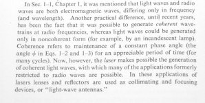
What is coherence?
I see there is a lot of confusion. Here in this image coherence is described in simple terms almost anyone willing can understand. The exact same concept applies to audio.
Minimum phase means the exact input can be derived from the output. In phase means staying in the same absolute polarity. Phase flipping means inversion of polarity of the output over a very small bandwidth.
Hope this helps!
🙂=SUM
Re: the minimum phase (MP) stuff people are talking about.
I'm trying to get my head around the MP / non-MP distinction and what it means for audio measurements with loudspeakers and rooms.
I've done the usual 'net searches (including Wikipedia) and they all get into high level maths really early in their explanations.
Does anyone have a straightforward physics/acoustics explanation for what MP means and how non-MP is different from it, that doesn't start talking about "zero poles in the unit circle"?
I suppose the teaching analogy would be like explaining some of Newton's laws using billiard balls on the snooker table rather than just showing the differential equations and saying "so there".😎
Any links or pithy text would be appreciated.
I see there is a lot of confusion. Here in this image coherence is described in simple terms almost anyone willing can understand. The exact same concept applies to audio.
Minimum phase means the exact input can be derived from the output. In phase means staying in the same absolute polarity. Phase flipping means inversion of polarity of the output over a very small bandwidth.
Hope this helps!
🙂=SUM
Attachments
Last edited:
Re: the minimum phase (MP) stuff people are talking about.
I'm trying to get my head around the MP / non-MP distinction and what it means for audio measurements with loudspeakers and rooms.
...
That link recommended by JohnPM above in this thread might be helpful:
http://www.hometheatershack.com/roomeq/wizardhelpv5/help_en-GB/html/minimumphase.html#top
---
http://www.diyaudio.com/forums/multi-way/166411-measurements-when-what-how-why-111.html#post2241491
Last edited:
Re: the minimum phase (MP) stuff people are talking about.
I'm trying to get my head around the MP / non-MP distinction and what it means for audio measurements with loudspeakers and rooms.
I've done the usual 'net searches (including Wikipedia) and they all get into high level maths really early in their explanations.
Does anyone have a straightforward physics/acoustics explanation for what MP means and how non-MP is different from it, that doesn't start talking about "zero poles in the unit circle"?
I'll try and give a workingmans definition of it but it won't be rigorously correct.
If a filter shape is made with the simplest circuit that will hit that shape, it will be minimum phase. If the phase response of a filter is the simplest or has the least delay possible to hit a response shape, it is minimum phase. If a complex circuit (or transfer function) has no all pass parts, it is minimum phase.
A simple ladder network is minimum phase. Non ladder networks with phase flipping lattices generally aren't. Individual drivers are generally minimum phase, multiway systems usually aren't.
The Hilbert transform defines the minimum phase phase response of a system. If the system's phase doesn't match that (or that plus non-dispersive delay) then the system isn't minimum phase. It contains an all pass element.
Minimum phase blocks in series or cascade are still minimum phase. Minimum phase blocks in parallel frequently aren't. Their combined function would require allpasses to simulate.
The subject came up because many network/system simulators import phaseless curves, do a Hilbert transform to define phase, and then will need interunit delays factored in. The Hilbert transform part is fine if we assume the imported bits were minimum phase. Otherwise the simulation isn't accurate.
In rooms, a measurement with a significant reflection (level seems to be a factor) will not be strictly minimum phase. Minimum phase systems can be perfectly equalized with minimum phase equalizers. Non-minimum phase sytems can be equalized flat but allpass errors (phase shift) will remain.
Now when the zeros move into the....sorry
David S
I think that link is showing some of the same erroneous thinking that has been in this thread.
This is quite interesting, because I'd like to get each driver to have as wide a band as possible to give me more flexibility where I place XO frequency. I do find that lots of curved cones are not optimally designed. I have started some analysis using 6.5 inch and 3 inch cones to see how good I can get them to perform. Initial Klippel scans show some interesting information, in some way in shows similar trends with FEM analysis, but can't seem to get them to match close enough.Actually, the curved cone woofer changes from piston mode to first drum head mode on purpose and in a very controlled way to allow large (and even small) drivers to have flat frequency response to higher frequencies. Virtually every PA driver has a curved cone for this purpose. Many consumer drivers have this also. Never mind the phase response, frequency response is all that matters. Altec even made a "bi-flex radiator" to exact this method and fix the phase flipping problem. Pretty much everybody does it now because marketing still lauds frequency response as the only important factor. Two ways are still cheaper than three ways and so on.
I hate them because it makes crossing over, sound quality, and use of the driver much more difficult than its straight cone cousin. Just one more thing I wish never was. But stupid is the rule...sadly.
Maybe I did not answer you question but using a curved cone woofer without FIR filters is a real problem as radiation is always incoherent in the phase flipping area- 200Hz for a curved cone 15 inch typically. Further, radiation above that frequency is out of phase with radiation below that frequency by 180 degrees. Anyone, put that effect in your crossover modeling slockware.
=SUM
Oh well.
One thing that I found during some measurements, is that the impedance phase of an air core inductor is different from a cored inductor. I'm sure this is going to have some effect on system performance, but I haven't explored it too much.
Last edited:
Excess group delay is, I believe, covered in detail in Joseph D'Appolito's "Testing Loudspeakers", but it is easy to explain - it is simply the group delay calculated from the excess phase. In a loudspeaker measurement context the main uses for excess group delay are to examine drive unit time alignment and to determine measurement delays to permit correct (delay-free) phase information to be displayed. As the excess phase is largely free of the response related fluctuations of the system measurement (except where those deviate from minimum phase behaviour) the excess group delay shows the time alignments and delays much more clearly than the measured group delay.I've heard of excess phase and group delay but not excess group delay.
The measurement would certainly be much cleaner in an anechoic environment, but it is misleading to say the spikes are computational artefacts - they are a faithful reflection of the behaviour of the measured system, including the contribution of the environment in which the speaker or drive unit was measured.These are for the planar speaker of post #1090, right? It appears that the curves were taken under non-anechoic conditions. As such the "hash" in the response curves give rise to similar hash on the phase curve. Differentiating the phase curve turns the high slope of the phase curve hash into sporadic spikes. It is a measurement and computational artifact. It is not a characteristic of the driver. (It would totally go away when measured under anechoic conditions.)
There is no autoscaling, but the plot does cover a large span. Here it is for a span 100 times smaller, again with no smoothing. The excess group delay is very flat above approx 2.5kHz because the measurement is very close to minimum phase in that region and hence measured phase and minimum phase move in concert.Another clue would be the level peaking to 150ms. The curves are flat between the spikes because the autoscaling has been dominated by the extremely high spikes, compressing any true info between the spikes.

That is a rather strange comment. The sound doesn't need to "go" anywhere to have a large group delay, the plot is showing us how the different frequencies in the measurement are affected. As a much simpler example, below is a measurement of the amplitude, phase and group delay of a simple 2nd order parametric filter, +6dB at 100Hz, Q=20. The group delay at the filter's centre frequency is a little over 43ms (excess phase and excess GD are zero for this example as this is an entirely minimum phase system).(At about a ms a foot, where would the sound go for 150ms?)


I hope that helps clarify excess group delay somewhat, though having read through some of the postings in this thread learning from one another does not appear to be high on the agenda.
...
One thing that I found during some measurements, is that the impedance phase of an air core inductor is different from a cored inductor. I'm sure this is going to have some effect on system performance, but I haven't explored it too much.
If you are referring to the lossy inductance of a drivers voice coil, this might be of interest,
if not already known
http://users.ece.gatech.edu/~mleach/papers/zobel/zobel.pdf
"Two simple Zobel impedance compensation networks for the lossy voice-coil
inductance of a loudspeaker driver are described. Design equations for the
element values are given, and a numerical example is presented."
Last edited:
I'm referring to inductors that may be used in XOs For example, impedance of two inductors of very close values:If you are referring to the lossy inductance of a drivers voice coil, this might be of interest,
if not already known
http://users.ece.gatech.edu/~mleach/papers/zobel/zobel.pdf
"Two simple Zobel impedance compensation networks for the lossy voice-coil
inductance of a loudspeaker driver are described. Design equations for the
element values are given, and a numerical example is presented."
An externally hosted image should be here but it was not working when we last tested it.
Note how the impedance phase differs?
Excess group delay is, I believe, covered in detail in Joseph D'Appolito's "Testing Loudspeakers", but it is easy to explain - it is simply the group delay calculated from the excess phase. In a loudspeaker measurement context the main uses for excess group delay are to examine drive unit time alignment and to determine measurement delays to permit correct (delay-free) phase information to be displayed. As the excess phase is largely free of the response related fluctuations of the system measurement (except where those deviate from minimum phase behaviour) the excess group delay shows the time alignments and delays much more clearly than the measured group delay.
Thanks for the explanation. I am used to seeing the terms independently but not together. I've never had trouble using group delay curves of systems to guage the delay in the woofer region, the delay in the tweeter region, and hence the relative arrival time differences.
The measurement would certainly be much cleaner in an anechoic environment, but it is misleading to say the spikes are computational artefacts - they are a faithful reflection of the behaviour of the measured system, including the contribution of the environment in which the speaker or drive unit was measured.
The context was "here is a driver and its measurements". The discussion then became whether it (the driver) was minimum phase or not. If the measuring environment was leading to a conclusion that the driver wasn't minimum phase, then I would consider that misleading. I still maintain, and it seems Earl agrees, that the spikes are as likely an artifact of the differentiation process. They certainly aren't characteristic of the driver.
I am also uncomfortable with a notion that the spikes in the excess group delay curve represent burst of non-minimum phase behavior and the flatter regions contained within are minimum phase. Most of the non-minimum phase systems I've seen would have an excess phase curve that would be definable by an allpass of some complexity, rather than seemingly random spikes. Just never seen that before. Perhaps I'm starting to agree with Earl here that acoustic response in a room isn't well suited to the MP notion.
That is a rather strange comment. The sound doesn't need to "go" anywhere to have a large group delay, the plot is showing us how the different frequencies in the measurement are affected. As a much simpler example, below is a measurement of the amplitude, phase and group delay of a simple 2nd order parametric filter, +6dB at 100Hz, Q=20. The group delay at the filter's centre frequency is a little over 43ms (excess phase and excess GD are zero for this example as this is an entirely minimum phase system).
Perhaps a bit of hyperbole on my part, and yes, high Q resonances can lead to rapid phase shift, hence large group delay. I'd still lay money that a number of delay spikes all near 150ms, is a computational artifact. What would you attribute it to?
I hope that helps clarify excess group delay somewhat, though having read through some of the postings in this thread learning from one another does not appear to be high on the agenda.
Indeed.
I'm referring to inductors that may be used in XOs For example, impedance of two inductors of very close values:
An externally hosted image should be here but it was not working when we last tested it.
Note how the impedance phase differs?
Check your imp. mag. scale. Should be log for starters. You should see the lower one being resistive instead of inductive at low f.
- Status
- Not open for further replies.
- Home
- Loudspeakers
- Multi-Way
- Measurements: When, What, How, Why