Quite amusing that this "minimum phase" issue keeps popping up. I think usage of this term is so mixed up that it's not even worth discussion.
But this I know (Bell Labs, Jont Allen): No matter what the characteristic of the source, its "room response" is not MP. That begs the question. If the source is MP, then at what point does it become non-MP? Does this happen at the first reflection? Second? gradually? All of a sudden? It seems pretty grey to me.
It was on the web:
http://www.music.mcgill.ca/~nils/cl...-Invertibility of a room impulse response.pdf
They concluded that the room response could be MP if the room absorption was sufficient (generally a reflectivity below 0.4 or a mean Alpha of above 0.6, fairly dead). It seems, as in one of your other posts, the level of the reflections are important, rather than just the presence of reflections.
David
Quite amusing that this "minimum phase" issue keeps popping up. I think usage of this term is so mixed up that it's not even worth discussion.
Perhaps thats why it is worth discussion.😉
Perhaps thats why it is worth discussion.😉
That meets my understanding of why something may need
to be dicussed. If we can figure out afterwards, in which cases
we need to care about MP and in which not, that would be helpful.
Only if working from magnitude only data would this occur ...
There is some software around which provides calculation
of MP information from magnitude data. "Use at your own risk ..."
But nevertheless it would be real nice, if we'd find some rules
of thumb - understandable for each of us - when assuming MP is
"quite save" and when it is not.
...
I understand that a breakup mode will be minimum-phase as long as the phase stays constant around a given radius.
What, if phase is changing from quadrant to quadrant of the baffle?
I believe I have seen pictures of such modes. Would that be minimum-phase too?
Rudolf
Those modes exist. (I guess Rudolf, you meant "membrane" instead of "baffle" ?)
http://www-hera-b.desy.de/people/nedden/lectures/06_07/musik/Vortraege/SoSe07_Trommeln.pdf
see page 5, quite self explaining although in german language.
I think Rudolf asked a justifyable question, since one criterion for MP
is causality. How is it determined, which sector of the membrane will vibrate
in phase and which in antiphase for those modes having node lines touching
the center ?
I am no FEM expert, but only the assumption of slight (even slightest) asymmetric
membrane properties should yield a definite result. Maybe the result is in fact
determined by limited precision of calculation (noise) ???
For the mode (0,1) of a drum membrane the node line goes through the center of
the membrane, separating it in two halves. How can one predict, which one will
vibrate in phase or in antiphase ?
Assumed this is like tossing a coin, can it be MP ?
Whether something can be considered minumum phase or not depends on the problem at hand. Theoretically, the term "minimum phase" should only be applied to relationship between single input and a single output. In acoustics problems, there will always be diffraction and reflections that mix with the output. Now, if we are not interested in the effects of these on the the output, then yes, you might be able to again understanding by simplifying the situation to a "minimum phase" model. If we accept the that diffraction and reflections influence the output to a concernable degree, then only the portion that eliminates these can be considered minimum phase.Perhaps thats why it is worth discussion.😉
So people will use the term to express what they want to regardless what others may think.😉
This would say that software such as LMS that uses pure swept sine should not be used because as a measurement system it does not measure phase. One must "tail" each measurement, then generate phase using the HBT. Were drivers not minimum-phase, this type of measurement would not work. The basic assumption is that the physics of drivers is such that they are minimum-phase devices.That seems odd since I don't see any reason that simulation software would have to assume MP, none of mine does. If the data is handled as complex from start to finish, it's being MP or not is irrelavent. Only if working from magnitude only data would this occur, and the solution is, well, trivial - don't do that.
Maybe I should put it this way. My understanding is that if the raw measurement were not M-P, then any typical design software would not work as the summed responses could not be reliably predicted, whether measured by MLS, swept sine or any other method.
I've used CALSOD since I started back in the 90's. One can use direct measurements to design, that much is obvious, but examining off-axis positions then requires manually calculating the change in excess-phase for each driver. However, if one creates an accurate M-P model of each driver's response that by its nature excludes all excess-phase and then enters the drivers into the coordinate system, multiple points in space can be examined and plotted simultaneously. Quick change for any point in space is as simple as entering the new coordinates to examine.
However, there's one more requirement to accurately reproduce the measurement(s) in space. That is that the relative acoustic offset must also be entered. The x,y coordinates are simple, they are the baffle placement. But the z-axis cannot be reliably nor accurately determined. In fact, it is a function based upon the model since the driver lowpass used in the model will affect the excess-delay. As long as the relative offset is correct (easily accomplished), the absolute centers do not need to be known. However, do determine the relative offset, drivers must be M-P. This is a recurring theme.
To go further, the method used by CALSOD is to create a flat response of the nominal sensitivity, then apply a set of what the software specifies as MPEs, or Minimum Phase Elements. This then creates each non-linear element in the measurement. One can have as rew or as many as desired to create the level of detail desired. In experiments I've had maybe 30 MPEs to create as close a match to the measured response as possible. It's not required, of course, for most design purposes. But it requires that drivers actually be M-P for this to be the case. It is a cascade of M-P deviations from flat, a magnitude and a Q. The sum is M-P, one or one hundred.
With the SPL magnitude the software then generates, via the HBT, an accurate M-P phase response with no excess-phase that then satisfies the requirements that allows for examining any point in space.
Go to current software, such as SoundEasy or any other software. The equivalent exists, only the newer software does most of this work for you. I suspect that most users are not even aware of what is actually being done by the software.
In the end, one does not program "minimum-phase" requirements into the software, it's a requirement that drivers actually behave in this manner for the software to actually work. That's what has allowed this type of software to be created in the first place.
I don't have the reference with me, but the author of CALSOD had a paper in the Journal of the AES submitted when he was initially creating his software describing his technique. His home page is here.
Dave
Last edited:
Just not correct. Easily disproved. Any time that you measure with SoundEasy and create a driver model to match the measured phase (if you've ever done that, try it if not), the result is the M-P of the response including all diffraction with some specified amount of excess-phase. I would expect you to be familiar with this by now.If we accept the that diffraction and reflections influence the output to a concernable degree, then only the portion that eliminates these can be considered minimum phase.
Dave
According to a page I found with a reference, the paper was in A.E.S Journal 9/88.I don't have the reference with me, but the author of CALSOD had a paper in the Journal of the AES submitted when he was initially creating his software describing his technique. His home page is here.
Dave
Last edited:
It was on the web:
http://www.music.mcgill.ca/~nils/cl...-Invertibility of a room impulse response.pdf
They concluded that the room response could be MP if the room absorption was sufficient (generally a reflectivity below 0.4 or a mean Alpha of above 0.6, fairly dead). It seems, as in one of your other posts, the level of the reflections are important, rather than just the presence of reflections.
David
Dave - Thanks for that. Its been years since I read that paper and I had forgetten that the MP thing was absorption dependent. Makes my argument even more plausible.
In the end, one does not program "minimum-phase" requirements into the software, it's a requirement that drivers actually behave in this manner for the software to actually work. That's what has allowed this type of software to be created in the first place.
Dave
Hi Dave
I'll stand by what I said because I have none of the problems that you suggest - but I don't use LMS (for the reasons you state) and I don't use CALSOD (ditto). Requiring MP IS because the programming made simplifications that today are simply not required. LMS has been obsolete for years. Use HOLM.
Theoretically, the term "minimum phase" should only be applied to relationship between single input and a single output. In acoustics problems, there will always be diffraction and reflections that mix with the output.
But it can still be a SISO problem - one source, one receiver - SISO.
I gave up on LMS (on loan) the first time I tried MLSSA (also on loan). I later purchased and still use LAUD. I tried HOLM and may try it a bit more, but LAUD suits my needs for most of what I do.Hi Dave
I'll stand by what I said because I have none of the problems that you suggest - but I don't use LMS (for the reasons you state) and I don't use CALSOD (ditto). Requiring MP IS because the programming made simplifications that today are simply not required. LMS has been obsolete for years. Use HOLM.
Would you describe those simplifications?
Dave
If phase is maintained throughout the process, via full complex calculations - then there is no need to assume MP for any source at any angle - or anything. If MP is required then the chain was broken somewhere.
Minimum phase and zero coherence
Been using the term coherence long before it became a buzz word. In this particular case the energy in the bandwidth is relatively constant through the transition range from plus to minus phase. The phase is indeterminate- it cannot be measured as it changes dramatically with tiny changes in frequency within the transition region. For a woofer to be "coherent" phase must be a continuous smooth function preferably a constant. What this translates to is the radiated energy in the transition bandwidth is useless to the ear and cannot be effectively equalized or decoded by the ear. For all practical purposes, noise.
Minimum phase simply means if I look at the output of the system I can determine what the input was given the transfer function. For most drivers this is true over a limited bandwidth but never true for the entire energy bandwidth.
As for measurement systems which do not accurately determine the excess time, the time from the stimulus signal to the time that stimulus is received by the detection system, before frequency response is measured can only generate an "energy curve" and do not provide vector information of energy with time. LMS does not. Many (most probably) do not. Making wild assumptions that drivers are minimum phase and thereby "assuming" a whole lot of things that are not true leads to "marketing curves" and statements which do nothing but cloud the facts. As long as one is assuming, why not assume a whole lot more things and save yourself from any bothersome testing?
Another method to measure phase is with a two tone or multi-tone tone test where the phase relationships between the tones are known. This was commonly done in earlier audio work and many other systems. This is still widely used in A/D D/A and radio frequency work. Very rudimentary stuff.
Originally Posted by gedlee
But this I know (Bell Labs, Jont Allen): No matter what the characteristic of the source, its "room response" is not MP. That begs the question. If the source is MP, then at what point does it become non-MP? Does this happen at the first reflection? Second? gradually? All of a sudden? It seems pretty grey to me.
This is an easy one- when the energy of the reverberant or early reflections exceed the energy of the direct sound. This assumes minimum phase existed initially as is the case with a live unamplified instrument or voice.
A few links on phase and two tone though did not find a clear description of the two tone method. The advantage of the multi-tone method is the value for excess time is not required. Any system which uses transforms such as impulse testing must measure excess time before useful results are available other than energy.
Chapter 2
ScienceDirect - Measurement : Analytical design of dual-tone signal for ADC phase-plane testing
IEEE Xplore is Under Maintenance
What is coherence? Sounds like a buzz word.
Rob🙂
Been using the term coherence long before it became a buzz word. In this particular case the energy in the bandwidth is relatively constant through the transition range from plus to minus phase. The phase is indeterminate- it cannot be measured as it changes dramatically with tiny changes in frequency within the transition region. For a woofer to be "coherent" phase must be a continuous smooth function preferably a constant. What this translates to is the radiated energy in the transition bandwidth is useless to the ear and cannot be effectively equalized or decoded by the ear. For all practical purposes, noise.
Minimum phase simply means if I look at the output of the system I can determine what the input was given the transfer function. For most drivers this is true over a limited bandwidth but never true for the entire energy bandwidth.
As for measurement systems which do not accurately determine the excess time, the time from the stimulus signal to the time that stimulus is received by the detection system, before frequency response is measured can only generate an "energy curve" and do not provide vector information of energy with time. LMS does not. Many (most probably) do not. Making wild assumptions that drivers are minimum phase and thereby "assuming" a whole lot of things that are not true leads to "marketing curves" and statements which do nothing but cloud the facts. As long as one is assuming, why not assume a whole lot more things and save yourself from any bothersome testing?
Another method to measure phase is with a two tone or multi-tone tone test where the phase relationships between the tones are known. This was commonly done in earlier audio work and many other systems. This is still widely used in A/D D/A and radio frequency work. Very rudimentary stuff.
Originally Posted by gedlee
But this I know (Bell Labs, Jont Allen): No matter what the characteristic of the source, its "room response" is not MP. That begs the question. If the source is MP, then at what point does it become non-MP? Does this happen at the first reflection? Second? gradually? All of a sudden? It seems pretty grey to me.
This is an easy one- when the energy of the reverberant or early reflections exceed the energy of the direct sound. This assumes minimum phase existed initially as is the case with a live unamplified instrument or voice.
A few links on phase and two tone though did not find a clear description of the two tone method. The advantage of the multi-tone method is the value for excess time is not required. Any system which uses transforms such as impulse testing must measure excess time before useful results are available other than energy.
Chapter 2
ScienceDirect - Measurement : Analytical design of dual-tone signal for ADC phase-plane testing
IEEE Xplore is Under Maintenance
I think it's simply a case of ease of setup for the user. With measured phase there may be a way to set up the coordinates that will do the same thing, but I don't see it as making simplifications. That, to me, implied that the software has known issues and that those simplifications create a problem. We are talking about software for sale to the general public, not designed by the user such as you. You know your needs and what you need to do to meet your goals. It's something else altogether to create it for use by the general public. In that regard, are you still saying that there are simplifications that are a problem? Or is it just methodology in the setup?If phase is maintained throughout the process, via full complex calculations - then there is no need to assume MP for any source at any angle - or anything. If MP is required then the chain was broken somewhere.
Dave
Been using the term coherence long before it became a buzz word. In this particular case the energy in the bandwidth is relatively constant through the transition range from plus to minus phase. The phase is indeterminate- it cannot be measured as it changes dramatically with tiny changes in frequency within the transition region. For a woofer to be "coherent" phase must be a continuous smooth function preferably a constant. What this translates to is the radiated energy in the transition bandwidth is useless to the ear and cannot be effectively equalized or decoded by the ear. For all practical purposes, noise.
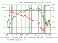
Have any measurements??
The phase is indeterminate- it cannot be measured as it changes dramatically with tiny changes in frequency within the transition region.
I have never seen that. Are you talking in break-up mode above the useable bandwidth?? Here's a 10" 2122 midrange driver. Looks fine to me. Where would the transition zone be in that driver?
Rob🙂
Attachments
I think you didn't understand what I'm talking about. If you accept that diffraction is of no concern to you, then you can use that data as minimum phase data. If you are trying to located the dominate source of diffraction, then you need to change the windows size to eliminate diffraction, in such case, the result will differ slightly. If such difference is of no concern to you, then you can use the wider window and assume it's the minimum phase data you use in further design work. If you still don't understand, I really don't know how to explain it in simpler terms.Just not correct. Easily disproved. Any time that you measure with SoundEasy and create a driver model to match the measured phase (if you've ever done that, try it if not), the result is the M-P of the response including all diffraction with some specified amount of excess-phase. I would expect you to be familiar with this by now.
Dave
You can treat it like that if diffraction and/or reflection, etc. does not effect the purpose of the data measured.But it can still be a SISO problem - one source, one receiver - SISO.
I'd like to just throw in another example. Normally, when we measure electronics devices, the noise is low enough that it does not effect how interpret the results, and thus, the response of the DUT to the input fits a minimum phase model. Now, if the noise level is high, such as may be caused by inproper grounding, we will find that the response of the DUT does not appropriately fit a minimum phase model, if we assume that it is a minimum phase model and try to modify the circuit for a particular response based on that kind of data, then we will not be able to do it, because the problem is not in our circuit model, but rather unique to the layout or grounding. So, regardless what the data will say, we try to modify the groudning and layout such that the DUT will respond in a minimum phase way that we expect the model to respond.
You think wrongly, I understand it rather well, thank you. Diffraction of baffles is a concern to anyone unless you are working with horns/waveguides. Why anyone would "accept that diffraction is of no concern to you" is, in any case, sidestepping the debate. It fails to address the point raised, that being that measurements of typical drivers on a baffle will by default include diffraction, if you're going to acquire a usable bandwidth and that this response is M-P. The diffraction time delays are simply too short to remove it and still have a usable bandwith, the result will not differ "slightly". What you are saying to do is nonsense.I think you didn't understand what I'm talking about. If you accept that diffraction is of no concern to you, then you can use that data as minimum phase data. If you are trying to located the dominate source of diffraction, then you need to change the windows size to eliminate diffraction, in such case, the result will differ slightly. If such difference is of no concern to you, then you can use the wider window and assume it's the minimum phase data you use in further design work. If you still don't understand, I really don't know how to explain it in simpler terms.
Dave
Last edited:
- Status
- Not open for further replies.
- Home
- Loudspeakers
- Multi-Way
- Measurements: When, What, How, Why