Peerless always supplied two sets of T/S parameters. One was free air, the other was mounted on an infinite baffle. The change due to the different air mass loading was apparent. This you could easily test yourself.Even when we talk about Vas, we assume that weight of air is almost nothing. Isn't that the case?
Were you to measure the impedance of a driver in a vacuum you could see the change in loss of all air mass loading.
Dave
I have never received two sets of T/S from Pearless. Of course the Q at resonance would change. It's also true that due to calculation and fitting, the Vas value will change; however, when ever we talk about Vas, the definition does not take air mass into account in the model.
I have a different process patent in China and Taiwan. Some effects I have shown in the EnABL thread. Simulation using Ansys was conducted to understand the modal changes, and later tested using the Klippel scanner. Quite incidentally, I asked about it right before it's first announcement in San Fransisco (if I remember correctly). If you want to know more about cone vibration, Ted Jordan had some articles on this subject in Wireless World back in the 80's.
Mark over here also has a good understanding on cone vibration.
http://www.diyaudio.com/forums/full-range/28355-markmcks-tang-band-mods.html
Thanks for that Soongsc. His site is very interesting. If you'd like to discuss your own process to any degree, I'm all ears.
I don't think Peerless does that 2 sets of data anymore. They used to for sure.
One other thing of interest when it comes to this delayed energy(seems an appropriate descriptor)and cone break up problems; Is most of the delayed energy caused by the break up, or is the spider also significantly involved? Is there any other significant contributors? It seems to me the spider could play a significant role. I'm tempted to dope it and measure the effects, but removing and replacing the drivers in my test enclosure is unfortunately time consuming. I'm sure I'll end up doing it eventually if I'm told it is a significant contributor.
OK, a couple other things:
If you were to double the size of the dustcap and it was of equal geometric and material stiffness of the original near the cone/dustcap junction, I'd assume the frequency where the break up begins would become significantly higher. Would you still have the same, more, or a reduced amount of delayed energy? I'd assume it would be reduced barring any issues in the dustcap itself, but I don't want to guess. It seems to me that the onset of break up should should be directly related to the size of the exposed cone given that its material stiffness is the same either way. Is there anyway to predict what new frequency the break up will start mathematically or is this too complex for any useful, simple prediction? Let's ignore all the problems the hypothetical dustcap would create at present. Anyway, I'm building dustcaps today and will do some measurements next week.
Thanks again,
Dan
If you use T/S parameters measured other than in a vacuum, it inherently includes the air mass loading.I have never received two sets of T/S from Pearless. Of course the Q at resonance would change. It's also true that due to calculation and fitting, the Vas value will change; however, when ever we talk about Vas, the definition does not take air mass into account in the model.
Dave
If you use T/S parameters measured other than in a vacuum, it inherently includes the air mass loading.
Dave
Here's a zip file with several web pages from Peerless back in 2001. Each has a separate set of columns for the T/S params unique to the loading.
I believe I saved these from the old Peerless site. I can't find anything in the current site.
Dave
Attachments
I don't get your point, Vas is a mechanical compliance not a mass, but no we don't assume the air is massless when we calculate the cone mass.Even when we talk about Vas, we assume that weight of air is almost nothing. Isn't that the case?
Air has mass at typical room condition of 1.209 gm/liter or 1.209kg/cubic meter. Air coupled to a moving flat diaphragm can become surprisingly high.
(16*1.209*radius*area)/(3*pi)=mass for round flat diaphragm
It is the mass of the air in a port which is used to resonate with the springiness of the air in the box for a ported systems coupled oscillator.
(16*1.209*radius*area)/(3*pi)=mass for round flat diaphragm
It is the mass of the air in a port which is used to resonate with the springiness of the air in the box for a ported systems coupled oscillator.
This mass loading is there in real operation. So that's why we use parameters that way. Definition of Vas is the same regardless.If you use T/S parameters measured other than in a vacuum, it inherently includes the air mass loading.
Dave
Not really interested in trying to explain it right now.Thanks for that Soongsc. His site is very interesting. If you'd like to discuss your own process to any degree, I'm all ears.
I don't think Peerless does that 2 sets of data anymore. They used to for sure.
One other thing of interest when it comes to this delayed energy(seems an appropriate descriptor)and cone break up problems; Is most of the delayed energy caused by the break up, or is the spider also significantly involved? Is there any other significant contributors? It seems to me the spider could play a significant role. I'm tempted to dope it and measure the effects, but removing and replacing the drivers in my test enclosure is unfortunately time consuming. I'm sure I'll end up doing it eventually if I'm told it is a significant contributor.
OK, a couple other things:
If you were to double the size of the dustcap and it was of equal geometric and material stiffness of the original near the cone/dustcap junction, I'd assume the frequency where the break up begins would become significantly higher. Would you still have the same, more, or a reduced amount of delayed energy? I'd assume it would be reduced barring any issues in the dustcap itself, but I don't want to guess. It seems to me that the onset of break up should should be directly related to the size of the exposed cone given that its material stiffness is the same either way. Is there anyway to predict what new frequency the break up will start mathematically or is this too complex for any useful, simple prediction? Let's ignore all the problems the hypothetical dustcap would create at present. Anyway, I'm building dustcaps today and will do some measurements next week.
Thanks again,
Dan
Whenever there is structural flexture, there is a delayed release of energy. How much delay occurs and how it relates with wave propogation is what changes the SPL response. I don't think there is a simple way to calculate it. In most cases, it's better to try and dissipate the energy before it is acoustically released after the delay. That's why Elac used some other material behind aluminum cone. Jordan drivers are designed with the appropriate mechanical properties that does the job very well without the damping material behind. There is nothing much one can do with the spider because of it's functionality, but this is where enclosure design will come in. If anyone remembers some of my posts in an enclosure thread, I was able to lower system resosnance frequency compared to free air.
Changing the size of the cap mainly changes the modes in the cone and cap. The interaction becomes complicated.
Last edited:
My point was, in almost all speaker modeling, distrubuted mass/compliance is not used. This is a significant limiation when we are trying to more deeply understand operation of speakers.I don't get your point, Vas is a mechanical compliance not a mass, but no we don't assume the air is massless when we calculate the cone mass.
I understand that, your question seemed more related to overall T/S parameters. Earl took it more literally.This mass loading is there in real operation. So that's why we use parameters that way. Definition of Vas is the same regardless.
Your post initially stated that "...we assume that weight of air is almost nothing" before asking "Isn't that the case?". My response was related to the air mass part of the question. You also replied that you'd never seen Peerless data with both measurements so I provided that.
But if you knew that "This mass loading is there in real operation", why did you even pose the question at all?
Dave
Cone breakup modes change from driver to driver in the same production run. Am not including situations like "drum head mode" in this statement as that can be somewhat controlled for consistent results. Examples are curved cone 15" woofers as found in today's PA and the "biflex" radiator of yesteryear~1975. Random breakup is for all practical purposes impossible to predict the pattern. Affecting the random breakup pattern can be done with cone edge treatment, surround material and treatment, and so on to every parameter of the moving and mounting system including the amplifier.
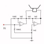
I have demonstrated on many occasions control of breakup by using a better amplifier much to many peoples surprise. Putting the voice coil in the feedback loop of a unity gain inverting amplifier really tames all breakup. See simple example of drawing. Power opamps.
I have demonstrated on many occasions control of breakup by using a better amplifier much to many peoples surprise. Putting the voice coil in the feedback loop of a unity gain inverting amplifier really tames all breakup. See simple example of drawing. Power opamps.
Attachments
My point was, in almost all speaker modeling, distrubuted mass/compliance is not used. This is a significant limiation when we are trying to more deeply understand operation of speakers.
I was reading about this in the LEAP5 reference manual today, serendipitously. 🙂
The LEAP5 transducer modeling has some special parameters to do this, but there are limitations to how fine a detail you can get.
The good news is this behavior is usually confined to the upper end of the frequency range (cone breakup), so the need to model this with great accuracy should not be super critical.
I don't know if this was this thread or not, where we talked about the first modal breakup, etc. It is critical to understand this one, and the importance drops above this one. The first mode determines the usable bandwidth and thus IMO becomes more important than rigid body mode, AKA T/S. This is why I don't give T/S modeling much importance. Hhen one uses a closed box, T/S is almost irrelavent. But that first breakup mode is still critical.
I don't know if this was this thread or not, where we talked about the first modal breakup, etc. It is critical to understand this one, and the importance drops above this one. The first mode determines the usable bandwidth and thus IMO becomes more important than rigid body mode, AKA T/S. This is why I don't give T/S modeling much importance. Hhen one uses a closed box, T/S is almost irrelavent. But that first breakup mode is still critical.
The first model breakup is the speed bump you use as an aid for determining your crossover point?
What other purpose might is serve?
If "breakup" includes changes from piston mode to first drum head mode (where the center moves out and rest (remaining outside "ring") moves back as example) then the curved cone PA speakers used today are operated far above the first mode frequency. I do not in my install but many (most?) of the driver manufacturers make these curved cone woofers (and midranges) for PA use. Actually pretty much all of the PA makers use these curved cone woofers because the on axis frequency response is more or less flat up to 1kHz and beyond for a 15 inch. In the first mode change region (typically about 200Hz for a 15 inch) the frequency response is often dead flat on axis even though there is a mode change. Random breakup occurs at a much higher frequency (>1kHz) in these curved cone woofers.
That's why so many people love the AE/Lambda TD15M. It has an admirable combination of a curved cone with a damping treatment, a phase plug to eliminate dust cap resonances and a well damped (but not over damped) accordian surround to reduce surround/cone-edge resonances. John doesn't get carried away with the damping so the sensitivity is still 98 dB.I don't know if this was this thread or not, where we talked about the first modal breakup, etc. It is critical to understand this one, and the importance drops above this one. The first mode determines the usable bandwidth and thus IMO becomes more important than rigid body mode, AKA T/S. This is why I don't give T/S modeling much importance. Hhen one uses a closed box, T/S is almost irrelavent. But that first breakup mode is still critical.
This is two of them unsmoothed in a horn MTM (woofers only). The LF stuff is room effects.
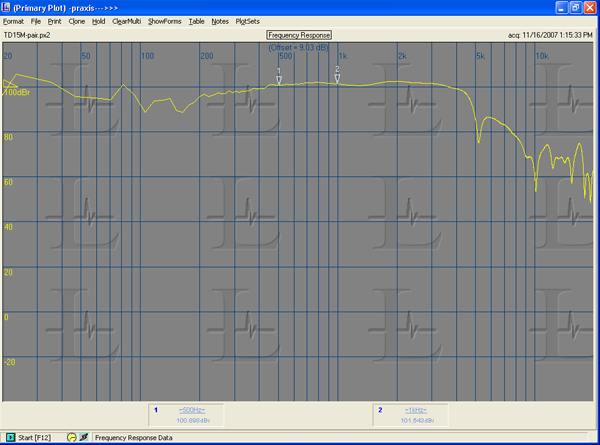
That's why so many people love the AE/Lambda TD15M. It has an admirable combination of a curved cone with a damping treatment, a phase plug to eliminate dust cap resonances and a well damped (but not over damped) accordian surround to reduce surround/cone-edge resonances. John doesn't get carried away with the damping so the sensitivity is still 98 dB.
This is two of them unsmoothed in a horn MTM (woofers only). The LF stuff is room effects.
I have a pair of the TD15Hs coming Wednesday. Looking forward to doing some measurements to see what all the fuss is all about. 😀
The TD15H has a roll surround so it's not quite as clean up high as the TD15M. But it plays a lot lower so it's better for a 3-way.
The TD15H has a roll surround so it's not quite as clean up high as the TD15M. But it plays a lot lower so it's better for a 3-way.
I am currently crossing at 400 Hz with my JBL 2235Hs to an Audax PR170M0 mid followed by a Morel tweeter, so I should not have that problem with the TD15Hs.
My worry is that the roll off for the TD15H will be too shallow and thus require a much steeper slope than a second order filter.
The only way to confirm that is to measure them and see. Currently there are no models for this transducer in LEAP5 and using the published T/S constants is not really good enough, so hi ho, hi ho, it's off to work I go - so I can pay for these puppies. Oh, wait... They are paid for! 😀
Hopefully, with some careful measurements and a little help from John I can get a good transducer model for these.
Last edited:
- Status
- Not open for further replies.
- Home
- Loudspeakers
- Multi-Way
- Measurements: When, What, How, Why