It's quite often that we catch only part of the discussion, isn't it.😉I understand that, your question seemed more related to overall T/S parameters. Earl took it more literally.
Your post initially stated that "...we assume that weight of air is almost nothing" before asking "Isn't that the case?". My response was related to the air mass part of the question. You also replied that you'd never seen Peerless data with both measurements so I provided that.
But if you knew that "This mass loading is there in real operation", why did you even pose the question at all?
Dave
I really was only referring to Vas. But the concept of T/S parameters is lumpsum, this would make it difficult to model some non-traditional concepts.
Last edited:
What is the highest breakup mode frequency you have dealt with using this concept?...
I have demonstrated on many occasions control of breakup by using a better amplifier much to many peoples surprise. Putting the voice coil in the feedback loop of a unity gain inverting amplifier really tames all breakup. See simple example of drawing. Power opamps.
I actually wish software would model the enclosure characteristics in a more distributed manner with any enclosure structure imaginable. I guess it won't happen in the next 10 years.🙁I was reading about this in the LEAP5 reference manual today, serendipitously. 🙂
The LEAP5 transducer modeling has some special parameters to do this, but there are limitations to how fine a detail you can get.
The good news is this behavior is usually confined to the upper end of the frequency range (cone breakup), so the need to model this with great accuracy should not be super critical.
This is what some simulation software will lead you to believe. In actual testing, I have not seen this mode.If "breakup" includes changes from piston mode to first drum head mode (where the center moves out and rest (remaining outside "ring") moves back as example) ...
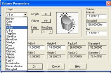
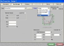
Take a look at LEAP or Bass Box Pro. Both have a rather extensive list of possible enclosure types. Can't imagine you needing more basic shapes than are available in them.
Rob🙂
Rob🙂
Attachments
Last edited:
I do believe this is only for internal volume calculation.😉Try simulating the Nautilus(for example)😀Or this:Take a look at LEAP or Bass Box Pro. Both have a rather extensive list of possible enclosure types. Can't imagine you needing more basic shapes than are available in them.
Rob🙂
An externally hosted image should be here but it was not working when we last tested it.
Last edited:
Not with LEAP it can simulate the polars as well and the environment and volume you the simulations in.
Rob🙂
Rob🙂
Try simulating the Nautilus(for example)
That's a unique exception although you may be able to get close. You don't really need to anyway. All you need is the measurements set and impedance runs with the drivers in the enclosure and you can do the crossovers from there.
Rob🙂
That's a unique exception although you may be able to get close. You don't really need to anyway. All you need is the measurements set and impedance runs with the drivers in the enclosure and you can do the crossovers from there.
Rob🙂
Last edited:
What is the highest breakup mode frequency you have dealt with using this concept?
Even in a two way through a crossover breakup of a 6.5 inch was greatly controlled at 2500Hz. With direct coupling to the driver breakup at any audio frequency is much more controlled with this scheme. This shows improved driver performance pretty much in every way.
Geddes is right, TL parameters are more or less useless for other than the very low frequency response and then only if the parameters are measured correctly. Using the impedance curve often leads to very different results than the driver actually is. Simply check to see if the mechanical resonance (peak in impedance curve) is the same frequency as the reflected electrical resonance (current and voltage in phase) to see how inaccurate impedance based results are.
This is what some simulation software will lead you to believe. In actual testing, I have not seen this mode.
Interesting... have seen this a lot. Try a little corn meal or white flour on the cone. Patterns appear quickly with the powder piling up at the node lines. Driver facing up....not vertical. Some times sawdust or talc works better. The right powdery substance will show node lines.
Last edited:
Are you sure it's a cone, not a flat panel driver? There is a big difference! I certainly would like to see someone do that on a cone driver.😀Maybe a metal one? Oh, BTW, metal cones will be somewhat different from paper cones.Interesting... have seen this a lot. Try a little corn meal or white flour on the cone. Patterns appear quickly with the powder piling up at the node lines. Driver facing up....not vertical. Some times sawdust or talc works better. The right powdery substance will show node lines.
Last edited:
The first model breakup is the speed bump you use as an aid for determining your crossover point?
What other purpose might is serve?
More like the other way arround. I knew where the crossover would be, I had to find a woofer that could get high enough without loosing control. It's actually pretty rare since most 12 & 15" drivers just aren't made to go to 1 kHz.
More like the other way arround. I knew where the crossover would be, I had to find a woofer that could get high enough without loosing control. It's actually pretty rare since most 12 & 15" drivers just aren't made to go to 1 kHz.
Actually "go to 1kHz" is the goal of PA 12" and 15" drivers. Now weather those drivers do that well is subject to a lot of interpretation but none the less this is clearly the goal.
Last edited:
Are you sure it's a cone, not a flat panel driver? There is a big difference! I certainly would like to see someone do that on a cone driver.😀Maybe a metal one? Oh, BTW, metal cones will be somewhat different from paper cones.
With the right powdery material this works with a "cone" driver also. Let me say I have made it work. I remember using sugar once also. Finding the right powdery material is part of the process!
As for cones here, these are "paper process" but made of lots of materials, fibrillated flax. kevlar, long fiber wood, short fiber wood, wool, and then several treatments. I going to assume you mean "paper process" cones and not simply paper. Straight paper cones are conical and have a seam. Paper is a press roll product. Paper process is kind of like the Greeks made paper 2000 years ago.
Make a slurry and suck it onto a mold and blow dry it, send it through a trimmer for the VC and surround. Dip it and spray it with various goops and then glue it to the rest of the parts. Paper process cone.
SUM, can you show a pair of graphs that demonstrates a voice coil in the feedback loop of a unity gain inverting amplifier taming break up?
edit: What are the drawbacks to doing this?
thanks,
Dan
BTW, my dustcaps are made. I should have graphs Thursday. I found out why these speakers all have such a unique break up behavior--their cones are geometrically uneven and all in different ways compared to one another. All of my other drivers are certainly close enough that I can't tell their degree of imperfection. To get these dustcaps to sit right is going to be a bit tricky. At first I thought it was my dustcaps, but they sit right on every other speaker.
Last edited:
The TD15H has a roll surround so it's not quite as clean up high as the TD15M. But it plays a lot lower so it's better for a 3-way.
Well the TD15Hs arrived today and John did a very, very nice job with the fit and finish with these drivers.
They are 8-Ohm VCs, but it actually is two 4-Ohm voice coils.
Now the bad news. I went to break these in and tried installing them into my cabinets. They don't fit!
The outside diameter of the machined basket is just a slight bit larger than the JBLs and will not fit into the recessed counterbore in the baffle.
So, back into the boxes they go. Due to personal weight lift limits I will not be able to modify the cabinets for quite awhile. This project may have to wait until the end of the year.
Thats a bummer for you 🙁
Yeah, I was going to redo the crossovers and I figured if I was going that far I should give the TD15H a try, but that looks like that is going to be off the table.
I may just stick with the JBLs and sell the TD15Hs.
I'd re rout the boxes and sell the JBLs.I may just stick with the JBLs and sell the TD15Hs.
- Status
- Not open for further replies.
- Home
- Loudspeakers
- Multi-Way
- Measurements: When, What, How, Why