Heck, to even get a decent-looking CSD you have to either be in an anechoic chamber or have to window out reflections after milliseconds of the start of the impulse response -- reflections TOTALLY destroy CSD appearance! I'm pretty sure that ears don't do this kind of windowing, so close in to the IR, in a usual home listening room.
I'd say that radiation pattern seems to me at the moment to be the most important (given that general response flatness can be dealt with by an equalizer if the off-axis isn't too far from the on-axis shape). Output level capability matters a lot, too, I think.
Hi Bill
The ear does do a sort of windowing, but you have to remember that its not a "microphone" that samples in time, it a spectrum device that samples in time (not discretely, but continuously - at least above 500 Hz or so). There are three basic regions of consequence in time - fusion (up to a few ms), precidence ( up to about 20 ms) and then "reflection" (everything else). The fusion region has a strong influence on imaging and the reflection region on spaciousness. The precidence reflections influence both in complex ways. My belief is that we must control the reflections and diffractions in the fusion region (for good imaging), while pushing out the reflections in the precidence region as far as possible (> 20 ms is not possible in a small room) and strongly reinforce all reflections in the "reflection" region (highly reverberant rooms, for good spaciousness). Given these requirements, the speakers directivity is pretty well dictated.
Surprisingly (or not!), your ratings of importance (polar and "output level" - mostly thermal to me) and mine are identical. Either we're both wrong, or its probably a pretty good bet on what's important.
Surprisingly (or not!), your ratings of importance (polar and "output level" - mostly thermal to me) and mine are identical. Either we're both wrong, or its probably a pretty good bet on what's important.
I do not think you are alone at all, I think everyone posting in this thread believes they are important. Are there designers that do not think those two are important?
I do not think you are alone at all, I think everyone posting in this thread believes they are important. Are there designers that do not think those two are important?
Everything is important. Until you rank order the importance and put a value on its "significance" you just talking semantics. There are lots here who openly state a disagrement with my order of priorities and their significance. Its not by neglect that I only mention two things - its because the others are not "significant".
Everything is important. Until you rank order the importance and put a value on its "significance" you just talking semantics. There are lots here who openly state a disagrement with my order of priorities and their significance. Its not by neglect that I only mention two things - its because the others are not "significant".
Thats fine.
Im a believer in constant directivity so the polar resonse is important. I also know all about dynamics and when I sit back 15 feet I know I need speakers that can hit the > 25dB peaks that exist in movies or music. Speaker SPL performance is important.
Now if Im building near field computer monitors neither of those will matter.
Priority can change based on the project requirements.
Actually there is a problem in the measurement setup where the mic clamp is reflecting some waves even though the clamp is about 45cm from the mic tip, and the clamp is about 80cm away from the vertical post.Thanks SONGSC for the side by side comparison. Its a great example of why I like CSDs.
I couldnt pick anything out from those FR plots (first 2, the 3rd is obvious) but the CSD gives me a choice.
One important thing to know is that looking at the different curves at different times will tell you whether there is any interaction, relfection, or diffraction going on. Depending on the time curve one focuses on, it's possible to go and verify the location by modifying certain shapes to see whether the response at that time changes or not.
Effects in the lowere levels cannot be seen in the SPL because normally the graphic resolution needs to be blown real big to see less than -40db of effects. Now some people may think this is unimportant. But we won't be sure unless we know truely what's causing it.
Last edited:
Priority can change based on the project requirements.
This is correct, but nitpicking. I assume the standard configuration that 90% of the people here will be using, not pro applications involving near field or HP line arrays, etc. which are entirely diferent animals. It would be unreasonable to assume anything else and just as unreasonable to have to qualify every statement made to its specific situation.
Now if Im building near field computer monitors neither of those will matter.
Priority can change based on the project requirements.
SPL is probably easier to achieve in that case but that doesn't change the priority of dynamics.
Directivity is even more important in near field monitoring because small head movements result in proportionally bigger axial changes when compared to "normal" listening distances.
This is correct, but nitpicking. I assume the standard configuration that 90% of the people here will be using, not pro applications involving near field or HP line arrays, etc. which are entirely diferent animals. It would be unreasonable to assume anything else and just as unreasonable to have to qualify every statement made to its specific situation.
Fair enough.
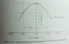
I do not know what to call the curves of post #262 but they do not meet the criteria for beamwidth measurement of the main lobe of radiation at a particular frequency of a single phase. This is the previously accepted standard for determining beamwidth from which directivity may be calculated. In antennas, the -3dB contour polar plot is used at specific frequencies to determine the beamwidth at that frequency. In audio it is often the -6dB contour and it beats me as to why the difference. The two attached images show a rectilinear plot instead of a polar plot and then a comparison plots where the data is the same. I find polar plots easier to visualize. For multiple frequencies multiple plots are required. I do not know what to call the plots of post #262 other than a "nice feature." There is no real indication of the directivity or polar information other than the measurement of response at arbitrary angles. This does not show the constant power contour of the transducer at particular frequencies. Please note, adjacent lobes will be always be 180 degrees out of phase with each other.
As for the tweeter I use that was designed and built over 10 years ago because so many were so tired of all the really bad tweeters in the marketplace. I mean ALL. The result was cooperation with a foreign manufacturer to build a tweeter with constant directivity (by the -3dB standard and not by the post #262 qualification) out to 30 degrees off axis which is the tweeter I use. Will say that only about 1 out of 3 pass all the test. I no longer have detailed data on the tweeter as it is very old. I will also say in the market place the tweet was very unpopular because it was not "flat" requiring EQ as all wideband constant directivity transducers do.
My question, "Is this (from post #262) what all the fuss is about waveguides?" It would be really useful and informative to see power contour plots at as many frequencies as practical per the previously accepted standard for measurement of beamwidth. This is extremely common in horn (and antenna) specifications. That would tell a lot about the waveguide. Plots like that for a standard open dome tweeter show just how lame that kind of tweeter is with it collapsing beamwidth and flat frequency response on axis. Wide band constant directivity audio transducers always require EQ to result in flat frequency response because to maintain the beam angle with rising radiation resistance requires more energy as the frequency increase. This is why a constant directivity horn contour EQ is already built into every DSP I use for those custom installs. Common knowledge for professional audio system designers.
I really do not care what these devises are named other than do not use a name which has a previously scientifically defined meaning and attach that name to whatever this should be called. Also, please, I really do not know if this device has constant directivity based on the information presented so there is no claim that these devices do not meet the standard criteria for constant directivity at some small angle.
One more thing, thanks for the explanation!🙂
=SUM
Attachments


Dan's point is that the off-axis response of the woofer at wide angles affects the system response there adversely, as he demonstrated here:
http://www.diyaudio.com/forums/multi-way/166411-measurements-when-what-how-why-23.html#post2189500
Why are we kicking about whether the waveguide he's measuring is a 60° or wider CD device?
Earl's aren't 90°, either, even when normalized:
Abbey
We've had the discussion as to what is and is not constant directivity here before, and the variability of results among different approaches to achieving it.
One member asserts that those which do it best somehow do not meet a contrived requirement for uniform attenuation with off-axis angle BECAUSE they are so good.
[Give me two weeks and I'll find this stuff. 😉 ]
My point in posting the Linkwitz image is to illustrate that, in conventional deployments of loudspeakers, the first and earliest lateral reflection, the one with the most potential to adversely affect both spectral AND spatial quality, comes from the range of Dan's concern. I had asked myself that question many times in the past, but never thought it through to the conclusion so clearly illustrated in that image....
Last edited:
in conventional deployments of loudspeakers
What would that be?
What's shown in the image, out from the walls and toed-in to the listening position. If they're back at the wall, the angle of the first reflection is similar....What would that be?
Why are we kicking about whether the waveguide he's measuring is a 60° or wider CD device?
Earl's aren't 90°, either, even when normalized:
We've had the discussion as to what is and is not constant directivity here before, and the variability of results among different approaches to achieving it.
My waveguides are called 90° because thats the angle of the walls not because thats the polar pattern that results. I think that this gets misunderstood.
Any can say that something is not CD just as anyone can say that just about anything is. There is no definition, but we all know the intent of the phrase. Yes, this has all been hashed over before. What is desired is the closest to CD that can be achieved. Its not necessary (nor possible) to be "perfect".
Don't get it - would you mind posting a drawing?
Attachments
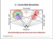
So what is your concern? A dipole will create a pronounced early ipsilateral reflection, the typical cone and dome speaker will create multiple attenuated lateral reflections and a waveguide speaker with higher directivity will provide maximum attenuation of early reflections.
As a point of reference to show plots for directivity as per standards please have a look at this informational brochure:
http://www.peavey.com/media/pdf/manuals/80300487.pdf
http://www.peavey.com/media/pdf/manuals/80300487.pdf
directivity as per standards
What standards? Earl's paper is probably a more up to date view on directivity http://www.gedlee.com/downloads/directivity.pdf
As a point of reference to show plots for directivity as per standards please have a look at this informational brochure:
http://www.peavey.com/media/pdf/manuals/80300487.pdf
Those are not standards, its a speaker brochure and it does not even look like those speakers have decent polars.
I have a comment about your past post with some tweeter that had amazing on and off axis. You are telling me that it doesnt exist now. It was an old tweeter that had great measurements but sucked SQ wise? How come when asked you will not produce the name of the tweeter or the measurements.
You should bring your own dip to the party if you are going to bitch about the dip the everyone is eating from. 😉
Last edited:
Here's a CD dome tweeter:
THE ART OF SOUND PERFECTION BY SEAS - Idunn
They're ~$50 apiece.
[It's done with diffraction.... 😀 ]
THE ART OF SOUND PERFECTION BY SEAS - Idunn
They're ~$50 apiece.
[It's done with diffraction.... 😀 ]
- Status
- Not open for further replies.
- Home
- Loudspeakers
- Multi-Way
- Measurements: When, What, How, Why