_Wm_ - so would I because ARTA never seem right o me. I suspect it is interpolating the angular data which smears the results. This is well know in pro standards, which is why the minimum spacing in the standard is 2.5 degrees. They do not allow interpolation.
I could live with ARTA as the main data taking software, but not their polar maps, because I don't think that they are right. You would have to make your rotating table design available, otherwise there isn't really any attraction - just commercial software instead of free.
I could live with ARTA as the main data taking software, but not their polar maps, because I don't think that they are right. You would have to make your rotating table design available, otherwise there isn't really any attraction - just commercial software instead of free.
Last edited:
I'd be very interested in using this even if it was as simple as just a list of file submissions for the different measurements and a "submit" button.
The interesting thing is the result, to get a seal of approval that "yes, your speaker is actually pretty good" or a "no, there is still a lot of room for improvement". Especially if we would get a lot of data, then us humble DIYers could browse the results and see what works and what doesn't to get the ideas flowing. And I would be okay with not being able to remove the submission, it would be nice as it ensures that those who use it share the result. If you decide the no delete route then it would be ideal to have some check for that the next result must be similar or it is saved as a new one to prevent people from just resubmitting and replacing with empty measurements to "remove" them. Or let people view all iterations but showcase the latest one, depending on how much space they take.
The interesting thing is the result, to get a seal of approval that "yes, your speaker is actually pretty good" or a "no, there is still a lot of room for improvement". Especially if we would get a lot of data, then us humble DIYers could browse the results and see what works and what doesn't to get the ideas flowing. And I would be okay with not being able to remove the submission, it would be nice as it ensures that those who use it share the result. If you decide the no delete route then it would be ideal to have some check for that the next result must be similar or it is saved as a new one to prevent people from just resubmitting and replacing with empty measurements to "remove" them. Or let people view all iterations but showcase the latest one, depending on how much space they take.
Last edited:
^ ... actually, something along these lines would be nice gedlee. If the design isn't optimal, a place to discuss with other diy'ers (like a subforum here perhaps) could be beneficial to all. Working to improve designs while alerting others to common pitfalls.
Only when we all have good data from which to converse can we get anywhere. With no data the "defender" always comes down to "Well it sounds good to me." and the conversation is over with no resolution of anything. No one learns anything and the general understanding of the masses does not move forward.
When you can say things like - "if you look at the data for xxx you will see how the smaller waveguide looses its coverage control at the crossover." Or, "note how the pattern beams from the larger driver in YYY." Then we have a common basis of discussion and understanding. It is impossible to do with no data and difficult when the data comes in various forms and is sparse or incomplete.
The better my measurements got the more my designs progressed. I could see the flaws, I could tell when they were getting better and when they weren't. It was like my eyes had been opened.
And I am not the only one who believes this. Harman is basically doing the same thing although they are definitely never going to make their system available. We differ is details, but not in the general and important aspects.
I'll try to find some time to get my waveguide speakers measured in your format.....it will be quite interesting to compare with my arta results. Mostly I'm interested in seeing how your sw shows data below 1khz. I'm always suspect of my gated in room measurements in this region so it would be nice if what you've got can give an accurate representation.
I see you have your sw modified to handle dipoles....I don't have them built just yet, but can you handle a cardioid-like speaker?
I see you have your sw modified to handle dipoles....I don't have them built just yet, but can you handle a cardioid-like speaker?
I did a stand too, but I put the two sliding boards on the floor because it allows me to place the rotation point exactly where I want and because it avoids the boards diffractions.
http://www.hostingpics.net/viewer.php?id=821668stand.jpg
http://www.hostingpics.net/viewer.php?id=821668stand.jpg
Last edited:
...I tailored what I have now to what I do. That does not mean that the approach can't handle a whole lot more. For example when I did the Orions I could not handle Dipoles, because the LF model assumed a monopole. I can now handle dipoles. I just had to turn of the monopole assumption...
Early versions of the Orions were dipole up to the tweeter crossover and monopole above. Does "turning off" the monopole assumption properly model a mix of mono/dipole? How about speakers that have frequency ranges with cardioid polar response?
With HOLMImpulse, you can speed things up using this simple script - see the link. The only thing left for manual action is to rotate the speaker during pause between the IR takes. You can just stand and wait somewhere nearby the speaker without any interaction with the PC. The result is a complete set of gated responses, comfortably taken, within a few minutes.
http://www.diyaudio.com/forums/software-tools/222198-holmimpulse-automated-measurements.html
(The latest version is in the last post.)
http://www.diyaudio.com/forums/software-tools/222198-holmimpulse-automated-measurements.html
(The latest version is in the last post.)
Last edited:
I'll try to find some time to get my waveguide speakers measured in your format.....it will be quite interesting to compare with my arta results. Mostly I'm interested in seeing how your sw shows data below 1khz. I'm always suspect of my gated in room measurements in this region so it would be nice if what you've got can give an accurate representation.
I see you have your sw modified to handle dipoles....I don't have them built just yet, but can you handle a cardioid-like speaker?
With a little thought I could. A dipole has no monopole term, a cardiod does, its just that the monopole term is lower than in a pure monopole.
Note the comment below on when these assumptions are used.
No matter what system is doing the analysis you need a reasonable reflection free window. If you only have 1 - 2 ms of before reflections you are not going to get decent results for most of the frequency range. You need more like 5 - 6 ms at least.
I did a stand too, but I put the two sliding boards on the floor because it allows me to place the rotation point exactly where I want and because it avoids the boards diffractions.
stand - HostingPics.net - Hébergement d'images gratuit
Yea that works, too. I suspect that it might be a little harder to make. As I said, the stand tends not to be a big issue.
Early versions of the Orions were dipole up to the tweeter crossover and monopole above. Does "turning off" the monopole assumption properly model a mix of mono/dipole? How about speakers that have frequency ranges with cardioid polar response?
There actually isn't ever a "turning off" of any of the modes, they are just assumed from a model - but only for those frequencies that are contaminated by the windowing - so for a monopole I assume the dipole term falls in accordance with the model. For a dipole I assume a slightly different model of an oscillating sphere - a dipole. It's not a big issue. This "assumption" is only in effect at low frequencies, typically 100-200 Hz in my system. Above that there are no assumptions made and everything is accurate.
With HOLMImpulse, you can speed things up using this simple script - see the link. The only thing left for manual action is to rotate the speaker during pause between the IR takes. You can just stand and wait somewhere nearby the speaker without any interaction with the PC. The result is a complete set of gated responses, comfortably taken, within a few minutes.
http://www.diyaudio.com/forums/software-tools/222198-holmimpulse-automated-measurements.html
(The latest version is in the last post.)
Thanks that might be handy.
_WM_
Is your table design available by any chance? Sounds interesting.
Hello Bwaslo,
Here a brief description that I once wrote as part of the manual for my software (I once had the intention of doing something with it, but unfortunately due to time and other restrictions I never got around doing this).
If somebody would make a hardware kit available (motor+pic+pcb+gear and bearing), I would be willing to write some software for it (PIC source code + DotNet code on PC) so that this table could be used with the posted script above. I would provide this as open source code also. It should however be a publically available kit, so many users here can benefit. So if somebody here is into selling and assembling kits, speak up.
Attachments
For a motor this could (most likely) be used (18$ per piece only!):
2pcs/lot Aslong JGB37 371 12v permanent magnet dc gear motor with encoder long life big torque free shipping-in DC Motor from Industry & Business on Aliexpress.com | Alibaba Group
There are many more on that website, just to give an example that this can be really low cost...
2pcs/lot Aslong JGB37 371 12v permanent magnet dc gear motor with encoder long life big torque free shipping-in DC Motor from Industry & Business on Aliexpress.com | Alibaba Group
There are many more on that website, just to give an example that this can be really low cost...
I think that without someone making the bracket and supplying the gear and bearing (which I have never seen before) and motor there would be few who would take this on. I mean really, I am no so lazy that I can't turn a speaker on a stand. It just isn't that time consuming. We did about 20 speakers here a few weeks ago in just a few hours. Setup time dwarfs all else.
No matter what system is doing the analysis you need a reasonable reflection free window. If you only have 1 - 2 ms of before reflections you are not going to get decent results for most of the frequency range. You need more like 5 - 6 ms at least.
Of course. Unfortunately about 3ms is the best I can do in my living room. I've been wanting to hang my speakers off my deck and get some good outside measurements. I'll try to do that this weekend.
Boom suspending a mic, azimuth adjustable, pivet set to the acoustical axis, controlled with a simple R/C servo/reciever. Wireless and easy enough to setup.
Not so lazy as much as work smarter not harder eg too much time on my hands and too many toys? 😉
Kickstarter a project with an automated servo controller, usb interface. I'm positive enough would be preordered to make it,... the next standard perhaps?
Not so lazy as much as work smarter not harder eg too much time on my hands and too many toys? 😉
Kickstarter a project with an automated servo controller, usb interface. I'm positive enough would be preordered to make it,... the next standard perhaps?
Greebster
I am not sure what you are stating, moving the mic instead of the speaker? Sure that works, but it takes a lot more room.
I don't follow your last sentence.
But lets not forget the need for low cost simplicity here. We are not trying to make a ANSI standard acoustic test lab.
I am not sure what you are stating, moving the mic instead of the speaker? Sure that works, but it takes a lot more room.
I don't follow your last sentence.
But lets not forget the need for low cost simplicity here. We are not trying to make a ANSI standard acoustic test lab.
gedlee said:No matter what system is doing the analysis you need a reasonable reflection free window. If you only have 1 - 2 ms of before reflections you are not going to get decent results for most of the frequency range. You need more like 5 - 6 ms at least.
That means the reflection must travel about 2m longer than the direct sound. For a two meter measurement distance, my mic needs to be 1.73m off the ground and below the ceiling - or 5.7 feet give or take.
So if our room is 8 feet tall, indoor measurements are a no-go?
_Wm_ - so would I because ARTA never seem right o me. I suspect it is interpolating the angular data which smears the results. This is well know in pro standards, which is why the minimum spacing in the standard is 2.5 degrees. They do not allow interpolation....it really does interest me to see the differences in polars between what you are doing and what is done by ARTA.
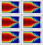
I recently calculated a polar data set with 1 degree increments for a 12" x 12" square ESL using the generalized Walker equation for far field response of a constant current driven electrostatic dipole radiator.
ESL simulator - technical background on Walker's equation
I then used ARTA to plot up sonograms(1/12 Oct smoothing) using different subsets of the total data set to see what is missed if polar data was only available with angular increments of 1, 2, 3, 4, 5, or 10 degrees. It sure looks like 2.5 degrees is probably a good estimate for the threshold at which smearing of fine detail starts to become obtrusive.
I still have all the impulse data. I could easily assemble the required subset of impulse data it into the format you use from Holm Impulse. Would you expect your process to be able to recreate something similar to the plot for the 1 degree angular increment?
Attachments
Last edited:
That means the reflection must travel about 2m longer than the direct sound. For a two meter measurement distance, my mic needs to be 1.73m off the ground and below the ceiling - or 5.7 feet give or take.
So if our room is 8 feet tall, indoor measurements are a no-go?
If all you have is an 8 foot ceiling then it is tough getting "good" data for larger speakers, but it's not that it is useless, it all depends on many other factors.
If the source and the cabinet are small then the spherical model for the LFs holds to a much higher frequency than it will for a bigger set like mine. I would not want to take this LF model much above 200 Hz in a big 15" system. But a small system with a 6" woofer could go to 400 Hz. and then a reflection free limit of 3 ms would probably be fine.
You understand that the closer you get to the source the greater you window will be.
Not using my techniques in a room with only an 8 ft. ceiling will surely yield poor data. With mine you just might get something worthwhile.
I could easily assemble the required subset of impulse data it into the format you use from Holm Impulse. Would you expect your process to be able to recreate something similar to the plot for the 1 degree angular increment?
Absolutely, I would expect a near perfect reconstruction, especially from noise free data.
- Status
- Not open for further replies.
- Home
- Loudspeakers
- Multi-Way
- Measurement technology