i mentioned the same similarity to a shotgun mic in our thread on the 34c9 but you dismissed it.
shotgun mic
Hi turk 182
sorry if I didn't reply to your post https://www.diyaudio.com/forums/full-range/341739-34c9-mdd-range-speakers-2.html#post5896352 but the shotgun mic looks very different from the speakers MDD. The main difference is the use of a single pipe. By replacing the microphone with a speaker I don't think there would be an efficient frontal acoustic load.
The Harry Olsen (RCA) microphone could be used as a MDD frontal acoustic load (MDDFL) by directly replacing the microphone with a speaker.
i mentioned the same similarity to a shotgun mic in our thread on the 34c9 but you dismissed it.
Hi turk 182
sorry if I didn't reply to your post https://www.diyaudio.com/forums/full-range/341739-34c9-mdd-range-speakers-2.html#post5896352 but the shotgun mic looks very different from the speakers MDD. The main difference is the use of a single pipe. By replacing the microphone with a speaker I don't think there would be an efficient frontal acoustic load.
The Harry Olsen (RCA) microphone could be used as a MDD frontal acoustic load (MDDFL) by directly replacing the microphone with a speaker.
Last edited:
Hi Gutbucket
With MDD technology, most of the sound energy emitted by the speaker enters the waveguides, passes through them and is reissued by acoustic diffraction with coherent, delayed and omnidirectional wave fronts.
How the output of the distributed sources, represented by the multiple pipe openings, interact with each other is the primary phenomena of interest in your design.
In Harry Olsen's (RCA) microphone a small part of the energy of the sound fronts in the environment enters the waveguides, only that emitted by a source in line with the waveguides can be detected by the transducer.
This is not an accurate description of the mode of operation of the microphone. Each pipe opening is equally sensitive to sound arriving from any direction (is omnidirectional sensitive), and contributes the energy transmitted through it to the microphone sensing element regardless of the direction of sound arrival. Increased directional sensitivity is a "group phenomena" imparted by the phase interactions in the sum of all tube outputs. For sound arriving on-axis with the tubes, where the path length from the source to the microphone diaphragm is identical through all tubes regardless of their lengths, the output of all tubes is in-phase and constructively sums at the sensing element. For sounds arriving from off-axis, the path lengths from the source through the tubes of various lengths differs, producing phase differences between the outputs of each tube, which constructively and destructively interfere to various degrees in the sum.
It is this phase-interference that reduces sensitivity off-axis, and from which the term 'interference tube' microphone is derived.
The design requires a sufficiently large number of path lengths which differ only slightly from each other such that the resonant peaks of each sum to produce an acceptably flat on-axis output response. Essentially what you mention here-
The presence of multiple guides in the MDD technology and in the Harry Olsen's microphone (RCA) derives from the fact that a single waveguide has minimum and maximum frequency response in the frequency domain. The frequencies of the minima and maxima depend on the length of the waveguides, with more waveguides of appropriate length the minima and maxima compensate each other and a linear frequency response is obtained.
The problem is that off-axis response sensitivity will not be flat but will vary across frequency AND by off-axis angle in a complex way. Although on-axis response can be made acceptably flat, off-axis response is always non-smooth and ragged, which represents the Achilles heel of any interference-tube microphone design.
I speculate that it is this non-uniform polar distribution of output response in the room (in the case of your speaker, which correlates with directional sensitivity in the case of a shotgun mic) that you are finding attractive. It is in effect flooding the room such that power response is flat, while the response at any one sampling point as compared to any another is ragged, within the effective bandwidth of the tubes.
Note that an interference-tube design can use a microphone capsule of any 1st order directional response, yet most choose a supercardioid or hypercardioid element as that defines the directional sensitivity across the lower frequency region. Directionality begins to increase beyond that of the microphone capsule (and along with it, the off-axis irregularities) above a frequency determined by the longest path length through the tube.
Last edited:
Hi Gutbucket
I don't know Harry Olsen's microphone enough to talk about how it works, so I leave the word to whoever studied it.
The microphone used UMIK-1 of the MiniDSP has the shape of a shotgun mic but is omnidirectional, as described in the datasheet.
MDD technology was born from empirical evidence that led me to the thesis that the reproduction of music is pleasant if the primary waves emitted by the speaker are followed by a series of coherent and delayed secondary waves. On a psychoacoustic level, they simulate for each instrument the presence of sound sources distributed in the space that reach the listener's ears with delays less than those of the reflections of the listening room.
I gave up on building a mathematical model for such a complex problem and I realized that the best results were obtained with a logarithmic length distribution. In the first prototypes with equal differences between the waveguides hissing sounds were heard. With lengths in logarithmic series also the differences are in logarithmic series and constructive or destructive interferences are distributed at specific frequencies on one or more octaves, the hissing sounds disappear.
My thesis derives from my tests and I am trying to improve the MDD speakers in order to entice other DIY to make replicas to compare myself on the listening impressions. At this moment the latest MDDXH135 and 22C71L8 prototypes have a very advantageous cost-performance ratio, they are omnidirectional, with the rear acoustic loading in spiral sheath (MDDBL) you can also build TLs up to 4 meters in small spaces.
Many "end address" style microphones have tubular bodies, but most use that to house the electronics and to suspend the mic element at the far end, in a position that is sufficiently acoustically distant from the mounting gear and wiring to minimize diffraction. "Shotgun" interference-tube mics are unusual in that their microphone element is positioned at the rear of the perforated multipath interference tube. Sort of opposite in terms of design.
One of the useful things about the Olsen multiple tube microphone design is that it helps to illustrate the multipath principle upon which all interference-tube shotgun microphones work. The principle remains the same when substituting a single tube designed such that it effectively produces the same multitude of paths from off-axis sources to the sensing element that the bundle of tubes of various length provide. With respect to microphones at least, a single tube with slots is far simpler, lighter, and less costly to produce than a bundled tube design.
It is very interesting how often the recording and reproduction sides of things parallel each other in some ways yet not in others. By example, regardless of its directivity pattern, the diameter of a microphone diaphragm and housing determines the frequency above which it's on-axis sensitivity begins to beam, in the same way that the diameter of a speaker driver determines the frequency above which its radiation will similarly begin to beam. Smaller drivers remain omnidirectional in their radiation pattern to a higher frequency just as smaller omnidirectional microphones retain uniform omnidirectional sensitivity to higher frequency in comparison with larger elements. Measurement mics are small in diameter so that their sensitivity pattern remains uniformly omnidirectional to a sufficiently high frequency.
But the similarity does not apply at the opposite end of the spectrum due to fundamental differences in sensing versus power transfer. As sensors, microphones are not faced with the air impedance mismatch "power transfer problem" speakers have. They don't need to efficiently couple with the air to transfer energy to it. A small diameter microphone diaphragm has no problem sensing low frequency pressure variations, while a sufficiently large speaker diaphragm (or some kind of impedance matching geometry such as a horn) is required to efficiently transfer energy into the air at low frequencies.
Another difference, specific to this case, is signal direction through the device, which should not be overlooked here despite the similarities mentioned previously. A more direct comparison of this speaker to an interference tube microphone would be individual drivers mounted at each of the distributed tube openings feeding a single combined output, producing a time-averaged output at a single point in space. Which would more directly correlate with the microphone example which features multiple arrival paths that combine at single sensor location.
By contrast, your design produces a spatially distributed output with phase variations across that spatial distribution. This is essentially the inverse of what an interference tube microphone is doing.
Thanks for the discussion!
Hi Gutbucket
thanks for thanks, it is a confirmation that Google Translator (with its limitations) allows me to explain the functioning of my MDD prototypes in English.
I have almost finished the possible MDD variants, I have to apply the open front loading (MDDFL) to the 3fe25 speaker. Then I will wait for other person to join the exclusive club formed by those who have listened to MDD technology. We are now less than 10.
Last edited:
I want to try and make a 2.1 system using a pair of Coral holy basket 4” fullrangers and an 15” dipole subwoofer. What MDD type would you recomend for the sateliltes?
I want to try and make a 2.1 system using a pair of Coral holy basket 4” fullrangers and an 15” dipole subwoofer. What MDD type would you recomend for the sateliltes?
Hello Pepe
the simplest way to make satellites omnidirectional is to replicate the MDDFL 21FL7 front load. Seven rigid PVC waveguides are positioned raised 10 mm in front of the speaker cone, the length is progressive in a logarithmic series (276, 305, 336, 371, 410, 453, 500 mm). If the satellites are to be placed on a desk, it is better to halve all the lengths, avoiding to send the energy of the high frequencies above the listener's head.
The rear load can be a sealed-box, a bass-reflex, a TL or an MDDBL rear load chosen from the MDD projects on the site. With a maximum length of 1000 mm it reaches 80 Hz, with 2000 mm at about 40 Hz.
To increase the perception of the 3D effect of coherent, omnidirectional and delayed secondary waves, the acoustic loads are positioned by imitating the shape of the letter "J". The short side of the J corresponds to the front load MDDFL, the long side of the J corresponds to the rear load MDDBL. The two groups of waveguides are connected at a distance of 300 - 400 mm, in this configuration the emission points are also spaced in the direction of the depth and not only in height. The distance in the lateral direction is ensured by the presence of the two stereo channels, right and left.
I'm preparing the documentation for a new project: MDD3FE25, I started listening yesterday. I still need 5-10 days to publish. To a 3FE25 speaker I applied the version with open front load of 300 mm in paper (short side J) and with a 300 mm fitting I connected the waveguides of the project 21M7 as a rear load, maximum length 1400 mm (long side J).
Attachments
Is the front loading of the MDDFL 21FL7 better then the 22c7?
I will most likely have to place them on the floor.
Will there be greate loss of 3d effect if the MDD principle is only covering down to 150hz~200hz and below that open baffle woofers will handle everything below that.
I will most likely have to place them on the floor.
Will there be greate loss of 3d effect if the MDD principle is only covering down to 150hz~200hz and below that open baffle woofers will handle everything below that.
Is the front loading of the MDDFL 21FL7 better then the 22c7?
I will most likely have to place them on the floor.
Will there be greate loss of 3d effect if the MDD principle is only covering down to 150hz~200hz and below that open baffle woofers will handle everything below that.
I suggested the 21FL7 open front load because since January I am used to combining it with a rear acoustic load. If rear loading is not available, it is easier to build the 22C7 directly.
The minimum reproducible frequency is influenced by the length of the shorter waveguide, the guides work in parallel and a guide much shorter than the others discharges those with longer length. The 276, 305, 336, 371, 410, 453, 500 mm series covering a single octave can be used, the lengths can be increased proportionally.
I also report here the links to the only MDD replicas of which I have news:
projects 22C7.V2 and 22D7 (modified) built by Kec,
34C9 project built by Pelanj.
The most important difference between 22C7 and 21FL7 and in the secondary wave phase. In project 22C7 the secondary waves emitted by diffraction are in counterphase with respect to the primary emission of the rear side of the speaker cone. In the acoustic load 21FL7 the secondary waves are in phase with the primary emission of the front side of the cone. I am unable to say whether the difference is perceptible to listening.
With secondary emissions, the MDD technology simulates the emission of sound energy in several points of the musical instrument distributed in three-dimensional space. The 3D effect simulates a virtual volume of the reproduced source, facilitates the recognition of the reproduced sounds. In projects 22C71L8, MDDHX135 and especially in MDD3FE25 (advance a couple of photos) the higher frequencies simulate a virtual volume with a maximum size of about 300 mm with front loading, short side J. The medium and low frequencies simulate a virtual volume of about 1400 mm with rear loading, long side J.
On a psychoacoustic level, I cannot say whether the hearing is more sensitive to the presence of coherent and delayed secondary waves in some frequency bands than others, the answer also depends on the work that other experimenters will do. Another field of analysis is the study of already widespread configurations such as the Karlson cabinet where the edges of the exponential profiles emit delayed and coherent secondary waves by diffraction. The open baffle panels on their edges emit delayed and consistent secondary waves. All the corners of the loudspeakers emit more or less coherent delayed secondary waves. The D'Appolito configuration emits delayed and consistent sound waves. The frequency distribution of the diffraction phenomenon is the most relevant aspect for the quality of listening. If anyone has material on the subject, report it.
Attachments

Thank you Claudiogan for the answeres and clearification.
I really do like the new MDD3fe25 project. I would defenetly like to try something similar with Coral holy baskets.
I really do like the new MDD3fe25 project. I would defenetly like to try something similar with Coral holy baskets.
MDD3FE25
The MDD3FE25 prototype ends tests on the MDD configurations that I have imagined. I am satisfied to have managed to make the best prototype with the 3FE25 speaker by recycling what I had available in lockdown, I did not buy a single screw. The appearance is still acceptable and will be easily improved with the stores open.
The only technical limitation of the project is on the length of the rear acoustic loading. I would have liked to use a maximum length of 2 meters, not being able to buy the material, I disassembled the 21M7 prototype only 1.4 meters long. When listening, the bass is not in the foreground as in the MDDHX135 and 22C71L8 projects, the 40 Hz are still heard. The response up to 15KHz has increased by a few dB and the sound is brighter, the 3D effect makes listening pleasant, the subsonic resonance bracket contributes to the overall cleanliness of the sound.
I am running the MDD3FE25 prototype with the best design for the Faital-Pro 3FE25 speaker. I'm curious to see if anyone has already done better.
The scheme of the project can easily be adapted to other broadband or coaxials.
Other links:
https://www.claudiogandolfi.it/
https://www.claudiogandolfi.it/mdd3fe25.html (with measures file)
https://www.claudiogandolfi.it/mddfl.html#61fl7
https://www.claudiogandolfi.it/mddbl.html#21bl7
Attachments
MDD3FE25b: 22FL7(22C7) + 21BL7
The 61FL7 front acoustic loading was ready when I built the first MDD3FE25 prototype. Its length of 294 mm is less than half of the shorter waveguide of the rear acoustic load 21BL7. To investigate the optimal length I first tried a shorter acoustic load, 200 mm, the audio quality deteriorated slightly. To test a frontal acoustic load with a maximum length similar to the guide shorter than 21BL7 I reused the waveguides of the 22C7 project. I only added four 30mm screws so that it could rest 20mm above the speaker. Audio quality has improved.
With the 61FL7 acoustic load combined with 21BL7 there are no secondary waves with delays between 1 and 3 milliseconds, it goes from 294 mm to 774 + 250 mm, a difference of 730 mm.
With the acoustic load 22FL7 combined with 21BL7 there are no delays between 2 and 3 milliseconds, it goes from 640 mm to 774 + 250 mm, a difference of 384 mm. The best combination tried so far.
Other links:
Claudio Gandolfi - MDD (Multi Delays Diffraction Loudspeaker)
MDD3FE25b
MDDFL 22FL7
MDDBL 21BL7
Attachments
Last edited:
MDD3FE25c: 23FL7(227H) + 21BL7
The MDD3FE25c prototype is an important step forward in MDD technology.
In the prototypes MDD3FE25, MDD3FE25b and MDD3FE25c the length of the open frontal acoustic loading varies, from 294 mm 21FL7, to 640 mm 22FL7, to 1070 mm 23FL7. In percentage terms, the increase between the first and second prototypes is greater than the increase between the second and third. Listening to the third prototype is much better than the other two. The difference is not due to the very similar frequency response or distortion, but to a specific aspect of the MDD technology.
In projects with double acoustic load: open front MDDFL and closed rear MDDBL I optimized the frequency response as if it were a mechanical and acoustic two-way independent system. In the time domain, the two acoustic loads generate two series of 7 sound fronts in successive and separate time intervals, one in phase and one in counterphase. The hearing must elaborate two series 7 of temporally separated sound fronts and reconstruct the origin of the sound which can be the same instrument.
In the MDD3FE25c prototype, the longest waveguide of the front loading 23FL7 (1070 mm) is comparable with the length of the shortest waveguide of the rear loading 21BL7 added to the base (774 + 250 = 1024 mm). In this case, in the time domain, the two sets of delayed sound fronts are partially overlapping and require only one processing, the recognition of the sound is simplified.
While listening to the previous prototypes, there remains a series of information that the listener cannot instinctively trace back to a specific instrument of origin. I thought it was the effects of residual speaker distortion.
In the MDD3FE25c prototype, the recognition of the sound is simplified, the lost information is traced back to minimal changes in the timbre of the instruments or to slight modulations of the sustained notes. The acoustic scene is simplified and increases the realism of the instruments reproduced, some words that were previously confused become recognizable, in the tails of the songs you can perceive sounds of minimum level that previously escaped. In this situation the residual distortion of the speaker does not disturb listening, at this moment I prefer the reproduction of the MDD3FE25c prototype to that of the MDDHX135 prototype which uses a speaker 10 times more expensive.
The MDD3FE25c prototype further reduces the sound decoding time, increases the time available to the listener's imagination and also increases the listening pleasure.
Other links:
https://www.claudiogandolfi.it/
https://www.claudiogandolfi.it/mdd3fe25.html#c
https://www.claudiogandolfi.it/mddfl.html#23fl7
https://www.claudiogandolfi.it/mddbl.html#21bl7
Attachments
Maybe I missed something, but what is the reason for the lower box being so long? Could the front and back pipes be closer together and the back pipes longer? I will be printing new holders for my Al tubes and scrap the wooden ones if they turn out well. I ordered some more 3FE22 drivers so that I can try the dual arrangement - in Al and 3D printed holders.
Also, with 3D printing, all the tubes could be most probably arranged into one tower - 5x5 tubes with any number of them fed by the back of the driver and the rest by the front of it (e.g. 12 by front and 13 by rear). I think that would look awesome, would that work acoustically?
Also, with 3D printing, all the tubes could be most probably arranged into one tower - 5x5 tubes with any number of them fed by the back of the driver and the rest by the front of it (e.g. 12 by front and 13 by rear). I think that would look awesome, would that work acoustically?
3D effect
Hi Pelanj
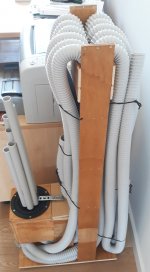
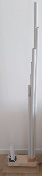
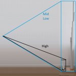
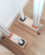
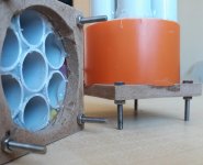
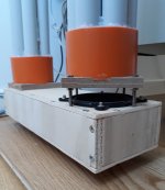
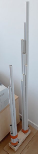
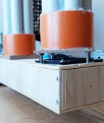
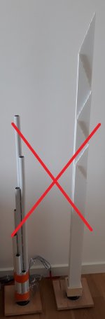
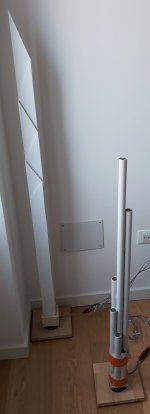
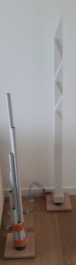
the base is 300 mm long to give depth to the sound scene. At the end of the page 54m42 - MDD project with alveolar polypropylene pipes. Version: Medium. I summarized with three photographs the best arrangement for a configuration with double driver and double acoustic load.
The double acoustic load is intended to optimize the frequency response. A group of waveguides use length and airtight assembly to best reproduce the low notes, MDDBL. The other group of guides is open, shorter and makes the house omnidirectional even at high frequencies, MDDFL.
If the MDDBL and MDDFL acoustic loads are positioned at the same distance from the listener, the sound image is 2D, you also reported it for your prototype with the 3FE22 driver, https://www.diyaudio.com/forums/ful...irectional-range-3fe22-build.html#post5959726.
By placing MDDFL closer to the listener, the sound image gains depth, it seems to me that listening improves as it is possible to attribute a virtual volume to the instruments reproduced. I call it a 3D effect and I appreciate it when listening. The configuration with double driver has already been created and customized also by Kec.
In the frequency domain, a compact base on which to mount MDDBL and MDDFL would have similar response and distortion measurements of a longer base.
In the time domain things change. With the longer base, the listener is able to perceive sound waves emitted in closer or more distant points, simulating a virtual volume of a musical instrument that emits sound energy in multiple points of 3D space simultaneously. These are not substantial differences but nuances. As a comparison, I think about the choice of fonts in road signs, changing a font means that in certain conditions of poor visibility, the probability of correct reading of the information increases. If you like a piece of music, it will continue as you like or vice versa. In optimal conditions, more details can be recognized.
In the MDD3FE25 project the compact base works well, I recommend it if the loudspeaker should be inserted in a furniture and must have a well-groomed appearance. If I want to experience the best possible sound with a driver, I prefer the longer base.
The 300 mm for the moment are the only test done, it could be even less but I haven't tried it yet.
Maybe I missed something, but what is the reason for the lower box being so long? Could the front and back pipes be closer together and the back pipes longer? I will be printing new holders for my Al tubes and scrap the wooden ones if they turn out well. I ordered some more 3FE22 drivers so that I can try the dual arrangement - in Al and 3D printed holders.
Also, with 3D printing, all the tubes could be most probably arranged into one tower - 5x5 tubes with any number of them fed by the back of the driver and the rest by the front of it (e.g. 12 by front and 13 by rear). I think that would look awesome, would that work acoustically?
Hi Pelanj
the base is 300 mm long to give depth to the sound scene. At the end of the page 54m42 - MDD project with alveolar polypropylene pipes. Version: Medium. I summarized with three photographs the best arrangement for a configuration with double driver and double acoustic load.
The double acoustic load is intended to optimize the frequency response. A group of waveguides use length and airtight assembly to best reproduce the low notes, MDDBL. The other group of guides is open, shorter and makes the house omnidirectional even at high frequencies, MDDFL.
If the MDDBL and MDDFL acoustic loads are positioned at the same distance from the listener, the sound image is 2D, you also reported it for your prototype with the 3FE22 driver, https://www.diyaudio.com/forums/ful...irectional-range-3fe22-build.html#post5959726.
By placing MDDFL closer to the listener, the sound image gains depth, it seems to me that listening improves as it is possible to attribute a virtual volume to the instruments reproduced. I call it a 3D effect and I appreciate it when listening. The configuration with double driver has already been created and customized also by Kec.
In the frequency domain, a compact base on which to mount MDDBL and MDDFL would have similar response and distortion measurements of a longer base.
In the time domain things change. With the longer base, the listener is able to perceive sound waves emitted in closer or more distant points, simulating a virtual volume of a musical instrument that emits sound energy in multiple points of 3D space simultaneously. These are not substantial differences but nuances. As a comparison, I think about the choice of fonts in road signs, changing a font means that in certain conditions of poor visibility, the probability of correct reading of the information increases. If you like a piece of music, it will continue as you like or vice versa. In optimal conditions, more details can be recognized.
In the MDD3FE25 project the compact base works well, I recommend it if the loudspeaker should be inserted in a furniture and must have a well-groomed appearance. If I want to experience the best possible sound with a driver, I prefer the longer base.
The 300 mm for the moment are the only test done, it could be even less but I haven't tried it yet.
Attachments
Last edited:
Could this device work as better plane wave tube with smoothed resonance? With compression driver from Fs to 3-4xFs?
- Home
- Loudspeakers
- Planars & Exotics
- MDD Multi Delays Diffraction (Multi TL, omnidirectional, single drive, ...)