Each of the four pieces of wire in the transformer primary has 1/4 of the total primary signal voltage across it. Can we agree on that?
No.
My measurements do not agree.
Attachments
No.
My measurements do not agree.
I see no reference point so it is not clear how you measured it. Between wich points did you measure?
I have never seen a composite load line of the unity coupled circuit, if you have, could you please share it?
You don't need to do that. You can use the pentode curves and then apply the feedback. Crowhurst did this all the time. You only need to know how triode, pentode and ultralinear work to figure out any other variation. In other words drawing load-lines for unity coupled is redundant that's why you never find it.
The plate and cathode windings are out of phase, no?
I have never seen a composite load line of the unity coupled circuit, if you have, could you please share it?
If the primary windings were out of phase (that is, in opposite polarity) they would cancel.
The point about a composite load line is that it is independent of things like whether and how much of the load is in the anode and cathode circuits.
All good fortune,
Chris
But your drawing shows four windings, each with 11.7 volts.No.
My measurements do not agree.
?
All good fortune,
Chris
No.
My measurements do not agree.
I think you do not add the 15.5 grid voltage. The grid voltage is just out of phase.
Adding the plat and cathode would be correct and give more than 1 for gain.
Today we did a further experiment.
What would happen if one of the output tubes would be removed from it's socket?
For sure the output transformer would lost DC current balance, so we had to do something for compensation.
First of all we checked some specifications and found out that our MC275 was not quite on spec; grid bias voltage was quite a bit lower than the specified -57V so there was rather high DC current through the tubes.
Replacing the rectifier diode in the bias supply cured the problem, and now we had -55V grid bias and a little over 30 mA DC current per tube.
The lower current also lowered the voltage gain of the tubes somewhat.
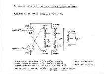
We fed the grids with 15 VRMS (instead of 15,5) and now all plates and cathodes had 10 VRMS (instead of 11,7).
The RMS voltage at the speaker output was 2,3.
All values referenced to ground.
To keep the output transformer in DC balance we soldered a 13k6 resistor (two 17W 6k8 resistors in series) between the plate- and cathodepin of the tubeless socket.
Then we again measured the AC voltages at the (remaining) grid, the four primaries, and the output.
Output voltage very slightly lower at 2,2 VRMS.
Grid voltage higher at about 22 VRMS.
All four primaries very slightly lower at 9,9 VRMS (the "live" primary perfectly couples the AC voltage to the "dead" primary because of the bifilar winding).
The higher grid voltage is caused by a change in feedback by removing one tube.
The loss in voltage gain I guess is caused by the lower load impedance by removing one tube.
However the output voltage after removing one tube is virtually the same.
What can we conclude?
For your reference once more the basic output stage.
What would happen if one of the output tubes would be removed from it's socket?
For sure the output transformer would lost DC current balance, so we had to do something for compensation.
First of all we checked some specifications and found out that our MC275 was not quite on spec; grid bias voltage was quite a bit lower than the specified -57V so there was rather high DC current through the tubes.
Replacing the rectifier diode in the bias supply cured the problem, and now we had -55V grid bias and a little over 30 mA DC current per tube.
The lower current also lowered the voltage gain of the tubes somewhat.
We fed the grids with 15 VRMS (instead of 15,5) and now all plates and cathodes had 10 VRMS (instead of 11,7).
The RMS voltage at the speaker output was 2,3.
All values referenced to ground.
To keep the output transformer in DC balance we soldered a 13k6 resistor (two 17W 6k8 resistors in series) between the plate- and cathodepin of the tubeless socket.
Then we again measured the AC voltages at the (remaining) grid, the four primaries, and the output.
Output voltage very slightly lower at 2,2 VRMS.
Grid voltage higher at about 22 VRMS.
All four primaries very slightly lower at 9,9 VRMS (the "live" primary perfectly couples the AC voltage to the "dead" primary because of the bifilar winding).
The higher grid voltage is caused by a change in feedback by removing one tube.
The loss in voltage gain I guess is caused by the lower load impedance by removing one tube.
However the output voltage after removing one tube is virtually the same.
What can we conclude?
For your reference once more the basic output stage.
Attachments

Today we did a further experiment.
What would happen if one of the output tubes would be removed from it's socket?
For sure the output transformer would lost DC current balance, so we had to do something for compensation.
To keep the output transformer in DC balance we soldered a 13k6 resistor (two 17W 6k8 resistors in series) between the plate- and cathodepin of the tubeless socket.
For your reference once more the basic output stage.
This is not necessary; the way the OPT is wound and the output tubes are configured, even with one output tube, the OPT is DC current balanced.
Try your measurements without the resistors and see what values you get.
Do this with low drive voltage so the amp is working in class "A" and then do the test with high drive voltage when the amp is operating in class "B".
Last edited:
What can we conclude?
Did you verify that the single tube is not clipping? Starting at a low quiescent current isn't going to allow much signal excursion.
But that is the near class B operating condition of the Mac. Although, it would be nice to get the voltage readings at full power output, i.e., 75W.Did you verify that the single tube is not clipping? Starting at a low quiescent current isn't going to allow much signal excursion.
But that is the near class B operating condition of the Mac. Although, it would be nice to get the voltage readings at full power output, i.e., 75W.
Right, but what are we trying to prove by taking one tube out and driving the other to produce a clipped waveform? We have voltage readings. Are they measured with a DMM or a scope? If measured with scope, can we see the waveforms? What are we trying to achieve by producing this presumably distorted waveform?
I'm wondering as well...😕Right, but what are we trying to prove by taking one tube out and driving the other to produce a clipped waveform?
Some things to consider....
Even when you pull one power tube... The associated cathode follower driver will drive that winding ..
You will see same voltage in all windings, due to auto-transformer affect...
The windings for the side without the tube will still show same voltages but a current probe will show no AC current flow in those windings...
Best way to kill the AC in one side of the P-P but still maintain balanced DC...is to lift the coupling cap that feeds the grid of the one follower driver valve..
Last edited:
Right, but what are we trying to prove by taking one tube out and driving the other to produce a clipped waveform? We have voltage readings. Are they measured with a DMM or a scope? If measured with scope, can we see the waveforms? What are we trying to achieve by producing this presumably distorted waveform?
No.
The waveform of the remaining tube was not distorted; the scope showed an unclipped waveform. Because of the low load impedance however the single tube stage very likely has considerable THD.
We wanted to check what would happen with AC voltages (measured with DMM), and therefore the voltage gain of the output stage, by removing one of the tubes.
The measurements confirmed what we expected:
- removing one tube does not change the voltage gain of the output stage, and this one tube voltage gain is about 1.5 (what a cathodyne stage is supposed to do);
- with both tubes, the normal situation, the voltage gain of the tube stage is about 0.75.
The initial question of the TO about voltage gain of the tube output stage is, at least for us, answered.
Last edited by a moderator:
Some things to consider....
Even when you pull one power tube... The associated cathode follower driver will drive that winding ..
You will see same voltage in all windings, due to auto-transformer affect...
The windings for the side without the tube will still show same voltages but a current probe will show no AC current flow in those windings...
Best way to kill the AC in one side of the P-P but still maintain balanced DC...is to lift the coupling cap that feeds the grid of the one follower driver valve..
And the associated plate follower will drive the other winding.
If you call the 1:1 tight coupling by bifilar winding an auto-transformer effect I agree...
Good suggestion to lift that coupling cap instead removing an output tube, but our method also worked well enough.
"- with both tubes, the normal situation, the voltage gain of the tube stage is about 0.75."
Where do you get this from? The voltage gain is still 1.5, the follower tube is still driving the other half of the AC cycle, although poorly. You cannot delete half the grid drive signal by pulling one tube out, it is still there on the follower tube.
Pulling one tube out does nothing useful for determining gain. All it does is reduce the gm severely for one phase polarity of the AC P-P drive.
Gain is about 1.5
Observable within the 1st few posts of this thread from measured data and several data sets thereafter. Observable by circuit inspection. Observable in all the documentation and articles written, including those by Mac.
Nothing but endless subterfuge and dead end diversions in this long thread. Just an example of the "last man standing thinks he wins the argument". This thread should not have been more than one page long.
-
Last edited:
- Status
- Not open for further replies.
- Home
- Amplifiers
- Tubes / Valves
- McIntosh bifilar output stage test proof