45: Yes, thats is logical and correct. Good point.
From electrical point of view. But if we assume the output stage as one complex including all windings, than this gain of 2 is used to make possible parallel connection of windings and in final creates no gain at all, right? So from different point of view the whole final stage gain is 1. I mean in gear ratio thinking or how to say it.
Well, if that is your point of view, why stop in the transformer core? The real output would be the secondary so the gain would be much much less than 1.
The truth is that the normal way to define gain in an output stage with or without cathode feedback (up to and including a cathode follower) is to compare input voltage to change in Va-k of the tube. That's why I define it that way. I can't see a compelling reason that the UC output stage gets to be different than all the others.
Well, I did what was easy for measurements today. I just used the breakout socket extender and tested with the speakers attached. I turned it up about as loud as I could stand and the input signal to the output tube grid under test was only about 2Vpk-pk (referenced to Gnd). Then I measured Va-k with a differential probe and there was ~3.5Vpk-pk signal there.
I'd have to get out the dummy load to test at higher levels, and I'd have to flip the chassis to measure current to see what the load is that the tube sees. I won't have time to do that until a weekend (I'm at the phase of life where I have small kids).
I'd have to get out the dummy load to test at higher levels, and I'd have to flip the chassis to measure current to see what the load is that the tube sees. I won't have time to do that until a weekend (I'm at the phase of life where I have small kids).
The schematic is correct ..The polarities are all good..
You don't show the AC current flow cycle ..
I see 2 windings in SERIES for each tube..
I don't see 4 windings are in SERIES, especially when you have the Plate winding and the cathode winding both connected at their AC electrical centers to ground...
You don't show the AC current flow cycle ..
I see 2 windings in SERIES for each tube..
I don't see 4 windings are in SERIES, especially when you have the Plate winding and the cathode winding both connected at their AC electrical centers to ground...
The schematic is correct ..The polarities are all good..
You don't show the AC current flow cycle ..
I see 2 windings in SERIES for each tube..
I don't see 4 windings are in SERIES, especially when you have the Plate winding and the cathode winding both connected at their AC electrical centers to ground...
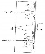
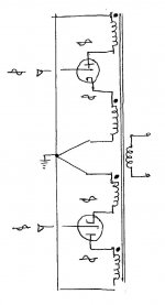
A better description than series or parallel is to say that a push-pull output stage is a bridge, with the primary windings as two legs and the valves as the other two legs. Viewed this way, the valves are in parallel for DC power but in series for signal (both input and output). In the McIntosh circuit this is still true, but harder to see. Here's a better drawing (sorry for the poor first one):
Attachments
Last edited:
Here is the McIntosh circuit simplified of power supply and G2's, showing signal polarities and how the four primary windings add:
Thanks for drawing this. I think this picture makes it easy to visualize my line of thinking for saying this output stage has a mu=2.
Each output tube (being that this is a class AB output stage, typically biased cold) contributes to the output for slightly more than half of the output waveform. The total peak voltage contributed by each tube across its two coils (added together because they are in series) is going to be a little less than the B+ (tube can only go down to saturation). Only a little over half of that peak voltage is delivered at the grid of each tube. Therefore, it has voltage gain (input being ground referenced input AC and output being AC swing on the primary windings).
Last edited:
The schematic is correct ..The polarities are all good..
You don't show the AC current flow cycle ..
I see 2 windings in SERIES for each tube..
I don't see 4 windings are in SERIES, especially when you have the Plate winding and the cathode winding both connected at their AC electrical centers to ground...
Yes, of course the two tubes work in parallel. That's how they keep working when one is cut off. But the plate and cathode windings are driven in series. This is what I have been trying to say in response to what you said earlier:
After designing transformers and winding MC output for around 30 years, I can tell you that the output stage and OT do not have real voltage gain...
Voltage Gain is approx .75 .....
This is due to the plate winding and the cathode winding are in PARALLEL and have identical AC signals across them during dynamic operation
You appear to have changed your mind? Or did I just not understand that you were trying to say this all along?
Yes, of course the two tubes work in parallel. That's how they keep working when one is cut off. But the plate and cathode windings are driven in series. This is what I have been trying to say in response to what you said earlier:
You appear to have changed your mind? Or did I just not understand that you were trying to say this all along?
I can see where the description interpretation is going sideways....
I always maintained that the 1/2 Plate and 1/2 Cathode winding associated with it's respective output valve is in SERIES...that is obvious..
What I mean by PARALLEL ....is that this Plate-Tube-Cathode series is in PARALLELL with the other Plate-Tube-Cathode series...
ie, (two windings in SERIES) in PARALLEL with the other (two windings in SERIES)....
I don't agree that all 4 windings are in SERIES....
Probably need to draw it out...using the simplified Thevenin AC equivalent..
Last edited:
I can see where the description interpretation is going sideways....
I always maintained that the 1/2 Plate and 1/2 Cathode winding associated with it's respective output valve is in SERIES...that is obvious..
What I mean by PARALLEL ....is that this Plate-Tube-Cathode series is in PARALLELL with the other Plate-Tube-Cathode series...
That becomes two windings in SERIES in PARALLEL with the other two windings in SERIES....
I don't agree that all 4 windings are in SERIES....
Yes, that's true of *all* push-pull output transformers.
I'm still confused why you maintain that this output configuration has no gain. It is obvious from Chris Hornbeck's drawing that this configuration will take half the input voltage of a cathode follower to induce the same AC voltage on the two series coils. Surely, this has twice the gain of a CF, right? And surely we can agree that a CF has a gain of ~1, right?
I don't agree that all 4 windings are in SERIES....
I don't recall anyone talking about 4 windings in series....
I don't recall anyone talking about 4 windings in series....
I've gone back and re-read some of my posts and I made some poorly-worded (incorrect) arguments in post #168. 😱
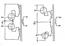
Here are two other variants, a conventional push-pull and a cathode follower push-pull. Note that the total number of primary windings is the same for both (for "optimum" loading). This is also true for any intermediate variation, including the Quad, the McIntosh, etc. The total number of turns is constant for any variation. Also note that being bifilar wound has no special loading effect.
All good fortune,
Chris
All good fortune,
Chris
Attachments
Last edited:
Yes, that's true of *all* push-pull output transformers.
I'm still confused why you maintain that this output configuration has no gain. It is obvious from Chris Hornbeck's drawing that this configuration will take half the input voltage of a cathode follower to induce the same AC voltage on the two series coils. Surely, this has twice the gain of a CF, right? And surely we can agree that a CF has a gain of ~1, right?
Looking at just one side of this output stage as if you have a Single Ended transformer or Cathodyne scenario... The Gain obviously is 2 unloaded...
Lets say 1V input at grid and 1V at the Cathode and 1V at the Plate...
Input to differential output gain is (1+1)/1 = 2 ....
However, when you have a MacIntosh P-P the input signal is applied differentially to both grids.. so now you have an equivalent 2 volt input signal to this output stage ....
Since both side of the transformer are in PARALLEL ..there will be no change in the voltage at the Plate and Cathode windings as there was with only a single ended tube... you will still have 1V at the Cathode and 1V at the Plate....
The only difference is the current in these windings will be double...and that is what I refer to as a CURRENT GAIN of 2 ...
But Voltage gain is (1+1)/ (1+1) = 1
Last edited:
However, when you have a MacIntosh P-P the input signal is applied differentially to both grids.. so now you have an equivalent 2 volt input signal to this output stage ....
Since both side of the transformer are in PARALLEL ..there will be no change in the voltage at the Plate and Cathode windings as there was with only a single ended tube... you will still have 1V at the Cathode and 1V at the Plate....
The only difference is the current in these windings will be double...and that is what I refer to as a CURRENT GAIN of 2 ...
But Voltage gain is (1+1)/ (1+1) = 1
By this line of reasoning a conventional push-pull amplifier is also "in parallel" and would have a turns ratio appropriate for that. Yet it doesn't. I suspect that the bifilar winding is being given some special weight that it doesn't have. It's still just turns of primary winding.
All good fortune,
Chris
However, when you have a MacIntosh P-P the input signal is applied differentially to both grids.. so now you have an equivalent 2 volt input signal to this output stage ....
Why do you start the first sentence with "however?" This is true of *all* push-pull output stages, including a cathode follower, and a push-pull cathode follower takes twice the differential voltage at the grids to clipping as the UC output stage does. Therefore, it has half the gain of the UC output stage.
Since both tube halves are in PARALLEL ..there will be no change in the voltage at the Plate and Cathode windings as there was with only a single ended tube... you will still have 1V at the Cathode and 1V at the Plate....
The only difference is the current in these windings will be double...and that is what I refer to as a CURRENT GAIN of 2 ...
But Voltage gain is (1+1)/ (1+1) = 1
I agree with the first part but not about the current doubling. DC current will be whatever you set it to by grid bias. The AC load will be shared between the two tubes since they are in parallel. Current will not be doubled. AC current will be smaller from the point of view of one tube when the second one enters the circuit. Again, this is true of *all* push-pull transformer-loaded output stages.
Edit: If you bias the output stage near class B, which is supposedly how most of these are biased (although not mine), there won't be much parallel operation anyway.
Last edited:
Why do you start the first sentence with "however?" This is true of *all* push-pull output stages, including a cathode follower, and a push-pull cathode follower takes twice the differential voltage at the grids to clipping as the UC output stage does. Therefore, it has half the gain of the UC output stage.
I agree with the first part but not about the current doubling. DC current will be whatever you set it to by grid bias. The AC load will be shared between the two tubes since they are in parallel. Current will not be doubled. AC current will be smaller from the point of view of one tube when the second one enters the circuit. Again, this is true of *all* push-pull transformer-loaded output stages.
Edit: If you bias the output stage near class B, which is supposedly how most of these are biased (although not mine), there won't be much parallel operation anyway.
Never meant the doubling of DC current...meant the SUM of AC current in the transformer winding is twice that of a single valve... You are assuming a constant power output...
I will make the voltage and current measurements one day and put on Youtube.. I did this these measurements 35 years ago and in agreement with Sidney Corderman the gentleman who designed the MC75 outputs, spoke with him on many occasion...
I don't think I am assuming constant power output. I'm just assuming that two tubes that share a load will have an easier time of driving it, not harder.
This is how I understand my own amplifier to work:
My UC transformer (wound by Plitron) has a turns ratio of 28.3:1 (14.1:1 for each primary), which is a higher ratio than the transformers wound by McIntosh. This is two 1.6k windings with the secondary loaded with 8 Ohms.
When one tube is cut off, the other tube works into half of the total turns, so will see a 1.6k load. When both tubes are conducting, they will each see a load of 3.2k, since they are working together. This is how all class AB push-pull transformer-loaded output stages work, whether the load windings appear in the anode, cathode, or are split between.
Since my amp is biased at ~50 or 60 mA per tube (can't remember exactly), I would expect to measure voltage swing at a current swing of +-25mA (from quiescent) in one of the output tubes that corresponds to it working into a 3.2k load. I can measure that and confirm it, it just might take a little while to get to it.
I could also draw a curved load line to represent the class A to class B transition and predict the peak voltages at, say, +200mA peak swing or more and measure that to see if my predictions are correct. All I'd need is the differential probe and a sense resistor.
I assume you disagree with some part of this. If so, what?
Never meant the doubling of DC current...meant the SUM of AC current in the transformer winding is twice that of a single valve...
Ah, now I understand your position. You're using the term "transformer winding" here to mean the paired wires of a bifilar winding, where each carries the current from one output valve. Others, including me, have used the term to mean a single piece of wire.
Each of the four pieces of wire in the transformer primary has 1/4 of the total primary signal voltage across it. Can we agree on that?
All four primary signal voltages are in phase. Can we agree on that?
All four primary signal currents induce secondary signal current in the same phase? Can we agree on that?
If so, then semantics has reared its little head. In the old days, folks would have drawn a composite load line and called it good; nowdays we spell into computers. Progress? Maybe some, but not guaranteed.
All good fortune,
Chris
The plate and cathode windings are out of phase, no?All four primary signal voltages are in phase. Can we agree on that?
I have never seen a composite load line of the unity coupled circuit, if you have, could you please share it?In the old days, folks would have drawn a composite load line and called it good; nowdays we spell into computers.
I don't think I am assuming constant power output. I'm just assuming that two tubes that share a load will have an easier time of driving it, not harder.
This is how I understand my own amplifier to work:
My UC transformer (wound by Plitron) has a turns ratio of 28.3:1 (14.1:1 for each primary), which is a higher ratio than the transformers wound by McIntosh. This is two 1.6k windings with the secondary loaded with 8 Ohms.
When one tube is cut off, the other tube works into half of the total turns, so will see a 1.6k load. When both tubes are conducting, they will each see a load of 3.2k, since they are working together. This is how all class AB push-pull transformer-loaded output stages work, whether the load windings appear in the anode, cathode, or are split between.
Since my amp is biased at ~50 or 60 mA per tube (can't remember exactly), I would expect to measure voltage swing at a current swing of +-25mA (from quiescent) in one of the output tubes that corresponds to it working into a 3.2k load. I can measure that and confirm it, it just might take a little while to get to it.
I could also draw a curved load line to represent the class A to class B transition and predict the peak voltages at, say, +200mA peak swing or more and measure that to see if my predictions are correct. All I'd need is the differential probe and a sense resistor.
I assume you disagree with some part of this. If so, what?
I mostly agree.....
I look at the two extremes... Class A and Class B ..
Looking at the traditional output stages..
In true Class B one valve is on at a time and utilizes 1/2 the winding, thus sees 1/4 the plate load...The source resistance is just the plate resistance of a single valve in 50% Duty Cycle...and vise versa...
transformer doesn't care which tube is ON between the two tubes alternating, the transformer sees just one "effective" source resistance ON 100% of the time...
For Class A both push-pull valves are ON and in series, thus the source resistance is plate resistance x 2 ...
Since ideal P-P Class A circuit is balanced..it will not pass any AC current through the Plate winding Center-Tap .... nor will any AC current flow from the Cathodes to the Plate Center-Tap via coupling cap....
If a common cathode bias resistor is used, a bypass cap would do nothing since there is no AC current flow in the Cathode...cancel at 180 apart.... So for Class A P-P we have a source resistance that is 2 times a single valve resistance and thus working into the entire Plate-Plate impedance...
I assume you already know this already...
My view is that Class AB is a superposition of the two of these operating Classes...
Based on where you bias in Class AB , the conduction angle will determine the amount of blend of the two..
So for small signal levels in Class AB amp, you are technically in Class A if your signal level hasn't forced either valve int cut-off as of yet.... just staying under the radar...depending how hot your biasing your tubes...
Once signals are increased the valves alternate in Class B mode working into 1/4 load for like 80% of the time....just making up a rough number ..actually depends on the conduction angle with respect to cut-off..
During the short time both valves are conducting you are technically in Class A and working into the full primary impedance..some will argue a true class A will not be possible without a full complete waveform cycle..
Last edited:
- Status
- Not open for further replies.
- Home
- Amplifiers
- Tubes / Valves
- McIntosh bifilar output stage test proof