Over the last few days I provided you with a couple of links to articles on the unity coupling principle.
Apparently you did not take the effort to take a look and try to understand; instead you "rely" on the opinions of some mr. Doc or "the ones you have talked to". This does not bring you one step further.
Apparently you did not take the effort to take a look and try to understand; instead you "rely" on the opinions of some mr. Doc or "the ones you have talked to". This does not bring you one step further.
Over the last few days I provided you with a couple of links to articles on the unity coupling principle.
Apparently you did not take the effort to take a look and try to understand; instead you "rely" on the opinions of some mr. Doc or "the ones you have talked to". This does not bring you one step further.
I'm not disputing what you are saying and I ordered a copy of the book you posted.. All I'm saying is there seems to be different opinions on whether or not it's a voltage amp and the guys that wind the trafos like Cerrem and Hoyer say there is no voltage gain. They both said you can't add the voltages being parallel windings and go on to explain why..Someone has to be right and someone has to be wrong.I agree that if you look at it as a cath PS it would be a 2 to 1 gain but for obvious reasons some say it can't be done that way.
Last edited:
That book is from the 1940's; McIntosh unity coupling design is from the 1950's.
Try to read into SY's suggestions.
I know it's from the 1940s and I ordered the other book..I just mentioned that's the only I book I had.
They both said you can't add the voltages being parallel windings and go on to explain why.
No! The cathode feedback in general is in series in fact the effective plate load is higher when connected.
Suppose you have a 2K primary plate winding and 16R winding for cathode feedback both referred to a 8R load. When cathode feedback is not connected then the plate load will be 2K; When the cathode feedback is connected the effective plate load will be [SRQT(2000) + SRQT(16)]^2= 2374 ohm.
The feedback factor beta will be SRQT(16/2374)=0.082 and so the closed loop gain Ac will be: Ac =Ao/(1+Ao*beta), where Ao is the gain open loop.
Finally the feedback ratio in dB's will be: Fb=20*log(Ao/Ac)
In a push-pull amplifier for a given output transformer you need to consider the effective plate-to-plate load which is different according to the class (A or AB, B)
Menno Van Der Veen also has a section on the Unity-Coupled output stage in his book. Also the Radiotron Design Handbook (fourth edition) has a brief treatment on pages 594-596. That one is easy to find for free on the internet. The best articles that I have found were by Norman Crowhurst, but can be trickier to find on the internet.
One thing to note in the example in the RDH book is that it notes that a UC transformer with two 1k bifilar coils present a load impedance of 4k plate-to-plate because they are driven in series, despite the fact that they are two parallel-wound coils.
One thing to note in the example in the RDH book is that it notes that a UC transformer with two 1k bifilar coils present a load impedance of 4k plate-to-plate because they are driven in series, despite the fact that they are two parallel-wound coils.
Last edited:
No! The cathode feedback in general is in series in fact the effective plate load is higher when connected.
Suppose you have a 2K primary plate winding and 16R winding for cathode feedback both referred to a 8R load. When cathode feedback is not connected then the plate load will be 2K; When the cathode feedback is connected the effective plate load will be [SRQT(2000) + SRQT(16)]^2= 2374 ohm.
I agree in that hypothetical scenario but the actual plate and cathode windings are not in series..Lets leave the FB out of it and just measure the output stage with a signal and a dif probe and see what happens.
Last edited by a moderator:
It's not hypothetical, it's the way it works.I agree in that hypothetical scenario but the actual plate and cathode windings are not in series..
They work in series regardless of SE or PP or Unity Coupled circuit. I made the SE example because simpler.
I think you cannot measure the output power of a MAC amp with the cathode feedback disconnected....this is hypothetical as I have never done it.Lets leave the FB out of it and just measure the output stage with a signal and a dif probe and see what happens.
What about doing this for now until I get a dif probe, suppose i just measure the signal between the plate and cathode of the output tube just and compare that to the input? Maybe we can see some kind of readings that are relatively close to 1.8 to 1 or 2 to 1. I would still be referencing the cathode to the plate but I will do this with the RMS voltmeter..Do you think it may work?
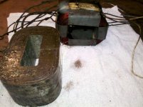
and it looks like a double C core.. I have 6 mc60s and a pair of Mc240s and a single Mc275 but,I thought the Mc275 and the Mc75 had similar OPT no?
That is a "single C core". Technically, you are right, but each "C" is only half of the "C" core.
This is a double "C" core:
Attachments

All the voltage gain in the McIntosh UC circuit comes from the first 12AX7, 12AU7 and 12BH7, especially the 12BH7. If you'll notice, the 12BH7's plates are not fed from the main B+ supply, they are fed from the B+ winding of the OPT. This is a neat trick that McIntosh did to get a lot of voltage swing from the 12BH7 stage. By connecting the 12K resistors to the OPT winding, the voltage supply to the 12BH7 is effectively 2 X B+, so the 12BH7 can swing A LOT of voltage. The UC circuit needs this because that 12BH7 is feeding 2 stages where there in no voltage gain, just power gain. The 2nd 12AX7 is a cathode follower, so there is no voltage gain there. The way the output tubes are configured in the UC circuit, there is no voltage gain there either, just power gain (current).
The other neat thing about having a split load in the output stage and OPT, is that it is so much easier to get the OPT quality factor very high with low impedance (relatively) OPT windings. 480 turns per half of primary winding is NOTHING. Most quality traditional OPT primary windings have 2000 or more turns in the primary.
One more thing... Output stages of tube amps typically don't have much, if any, voltage gain. This especially holds true for the McIntosh UC circuit.
That's how I see it as well but many of my buds are trying to convince me otherwise and if I don't see this another way,they may send me a letter bomb and will eat all the Christmas cookies and drink all the ale before I get there.
and it looks like a double C core.. I have 6 mc60s and a pair of Mc240s and a single Mc275 but,I thought the Mc275 and the Mc75 had similar OPT no?
Thats a SINGLE C-CORE ...
Not a Double C-Core..
Ask next time you take photos from my website, that is the usual protocol...
The MC60 and MC75 are almost the same OT ... The MC60 OT is beefier while the MC75 is more prone is shorting....
The number of turns changed over several revisions...MC outputs were not anal about the number of turns since they had a ton of headroom already... When they updated the MC75's with better wire coatings, they couldn't fit as many turns... The general rule at MacIntosh was to max out the number of turns that could fit the core window...
The MC biased cold close to Class B...but still AB1 amp... most of the dynamic action in the OT is similar to a class B circuit where only one side is on... then you measure the "auto-transformer" effect in the other windings..this is why its not really in series like a class A amp...also the plate is connected to the opposite end of the plate winding...thus putting the cathode and plate in parallel..
Last edited:
OMG I didn't even know that was your website, I just did a web search..I have no problem tho.I wasn't sure if it was 1 or 2 as it looked like a crease down the middle.
but many of my buds are trying to convince me otherwise and if I don't see this another way,they may send me a letter bomb and will eat all the Christmas cookies and drink all the ale before I get there.
What many are trying to tell is that the output stage gain is more than unity because both plate and cathode contribute to the output. This happens despite the fact there is 100% cathode feedback. 100% cathode feedback only means that cathode and anode windings have the same turns.
A simple example: Cathodyne phase splitter. The overall gain of this phase splitter is a bit less than 2 despite the fact there is 100% feedback because from one input one gets two outputs that are EACH approx 0.9 times the input and out of phase. So in total is 0.9+0.9=1.8 times the input.
In the MAC the driver has to deliver a peak voltage that is the bias voltage + the cathode voltage of the power tube to get 2X cathode voltage output (half at the cathode and half at the plate). So unless one uses a very low gain power tube, the gain is more typically somewhere between 1.5 and 2. It is a HALFWAY cathode follower. It's unity-coupled NOT unity gain: plate, screen-grid and cathode all swing equal amounts of voltage and phasing is such that screen-grid and cathode are in phase between them and out-of-phase to the plate.
A possible (almost) unity gain stage would be a cathode follower where the plate is supplied directly from the PSU and only cathode and screen are connected to the their own (identical) windings of output transformer. In such case the driver will have to provide the full output voltage and even a bit more (i.e. the bias)....
By connecting the 12K resistors to the OPT winding, the voltage supply to the 12BH7 is effectively 2 X B+, so the 12BH7 can swing A LOT of voltage.
No. The main reason for that is bootstrapping. Of course a relatively high supply voltage is necessary to swing all the necessary voltage but is not the main reason. Bootstrapping effectively multiplies the plate load. As the plate load is effectively multiplied a smaller plate resistor can be used and thus more anode voltage is available for the same or higher anode current. For example, if one has to drive a unity coupled power stage biased at -35 volts and has to swing 300V peak in the cathode, the driver has to provide 335V peak. Suppose the driver has 10K plate resistance, 500-550V is available both from the transformer and directly from the PSU and one wants the driver to run at 10 mA. With bootstrap a 10K plate load and 10 mA current will take 100V only. Bootstrap is positive feedback and once it is introduced the effective dynamic plate load will be 335/35=9.57 times 10K (i.e. 95.7 K!). If you use a 95.7K plate resistor from the 500-550V PSU voltage you will never be able to run the driver at 10 mA.
The trade-off will be higher Zout of the power stage.
Again the 12BH7 doesn't provide the full output voltage. It provides the bias + cathode voltage. The full output voltage is 2x the cathode voltage, the other half coming from the plate.
Last edited:
Equivalence of the Mac circuit to the Circlotron circuit:
The windings on the Mac that are bifilar and "unity coupled" are the SAME WIRE on the Circlotron. The Mac just uses two Circlotron windings on the same OT so that a single B+ source can be used.
This most likely leads (apples to apples) to a SQRT(2) performance increase over a conventional P-P CT'd OT for the Mac, and a 2x performance increase over a conventional OT for the Circlotron. (the Mac has 2x the wires taking up space on the bobbin) [this is comparing the OTs ONLY, however; common mode capacitance in the Circlotron floating power supplies can re-equalize the performance if not kept to a minimum with split power xfmr bobbins]
Attachments
Last edited:
The article Crowhurst wrote specifically about the Mac implementation was in Audio, Nov 1959. I think it was reprinted in one of the AudioXpress "Audio Anthologies.," but I'm not sure of that. If no-one can turn it up, I'll see what I can do about scanning it.
- Status
- Not open for further replies.
- Home
- Amplifiers
- Tubes / Valves
- McIntosh bifilar output stage test proof