Now i have done some more expriments.
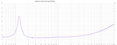
Reduce the volym to ca 5 liter netto ( with bags of rise)
FS raised to 123 hz and 150 hz "impedance blip" is still there but weaker.
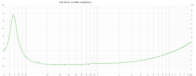
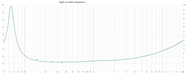
Also put both new drivers on the table and did a impedance mesaure, both have the same "impedance blip" at 148 hz.
The "Right" driver used a little have FS 64 hz mesaured at the table, the "Left" unused one have 68 hz with a blip.
Wonder if this pair have some small manufacturing defect, or if the blips disappears if i running them in for a few more hours with tones?
Scan Speak i tought was "King-drivers" ?
Regards John
Reduce the volym to ca 5 liter netto ( with bags of rise)
FS raised to 123 hz and 150 hz "impedance blip" is still there but weaker.
Also put both new drivers on the table and did a impedance mesaure, both have the same "impedance blip" at 148 hz.
The "Right" driver used a little have FS 64 hz mesaured at the table, the "Left" unused one have 68 hz with a blip.
Wonder if this pair have some small manufacturing defect, or if the blips disappears if i running them in for a few more hours with tones?
Scan Speak i tought was "King-drivers" ?
Regards John
Attachments
I would still say that's interference problem with your measurement setup.
More interesting is the difference at 900Hz and 1,2kHz - both are pretty low but it's not a "perfect" driver.
More interesting is the difference at 900Hz and 1,2kHz - both are pretty low but it's not a "perfect" driver.

Yes, definitely.I would still say that's interference problem with your measurement setup.
You have wiggles at 50, 100, 150, 250, 350 ... hz (mostly odd harmonics of mains frequency).
I once had a similar problem, because my measurement signal cable (the soundcard output stimulus cable) was going around the amp, picking up smoothing cap charging pulses.
It looks like some anomaly caused by the A/D conversion being spaced like that. I still believe the first plots you made show resonances from the enclosure. I've seen this on mine as well in various places with different enclosures. The other thing to try is getting the VC warm by running a 4V sine wave at 200 hz for about 10 min. If they both have the issue only in an enclosure, then its dependent on enclosure dampening issues. Free air resonances in the lower 100s are usually caused by spider issues and rarely by VC rocking or rubbing. Being the VC is open to contaminants getting into the gap, its really important to thoroughly clean and inspect the cabinet and dampening material for anything which can make its way into the VC gap.
I've used the same drivers a few times and haven't had issues like the impedance peaks you observe, but with mine some run in was required to closely duplicate the factory impedance curve with reduced magnitude radial surround reflection peak.
These drivers are some of the best cone mids I've heard at any price, especially in the lower mids. They have a pure, clean tone with excellent transient behavior. I've gotten the best sound from them with 6 dB HP filters at 250 hz crossed to a good 12" or dual 8 - 10" woofers. I dont like the sound of filters steeper than 1st order in the lower mids. 2nd order LR sounds pretty good and improves power.handling, but there is some degradation of accuracy in terms of transients and the blending of woofers to mids. The mids are highly revealing drivers and will shamefully expose poor recordings.
I will work more on investigating cables/earth etc, and also mesaure some other drivers i have.I would still say that's interference problem with your measurement setup.
More interesting is the difference at 900Hz and 1,2kHz - both are pretty low but it's not a "perfect" driver.
Regards John
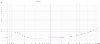
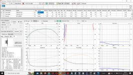
Every "bump" is my homemade impedance_rigg error, even a 3,3 ohm resistor get a "bump" at 148 hz.
Most bumps clear if i use "var smooting", but not the 148 hz bump.
Made the impedance_rigg with things i had home, but it seems sensitive for picking up cap charging pulses and others.
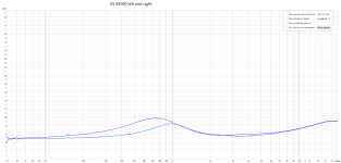
This is both tweeters SS 93000 impedance, both SS M18 and a 3,3 ohm resistor.
So impedance-rigg works, but are not "perfect" ;-)
Back to SS M18 cabinette testing, liters and filling.
Around 4 liters and well stuffed 140 hz LR2 was Loyzek´s advise, so aiming for that or near 👍
Regards John (boss over the dishcloth)
Most bumps clear if i use "var smooting", but not the 148 hz bump.
Made the impedance_rigg with things i had home, but it seems sensitive for picking up cap charging pulses and others.
This is both tweeters SS 93000 impedance, both SS M18 and a 3,3 ohm resistor.
So impedance-rigg works, but are not "perfect" ;-)
Back to SS M18 cabinette testing, liters and filling.
Around 4 liters and well stuffed 140 hz LR2 was Loyzek´s advise, so aiming for that or near 👍
Regards John (boss over the dishcloth)
Attachments
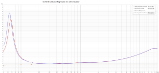
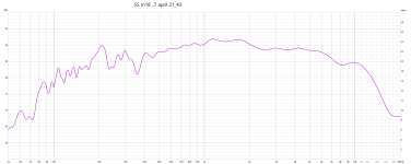
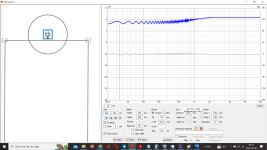
You should be getting world class midrange from this unit, just fix this 50 Hz noise in your equipment.
18M has titanium former, treated, much stiffer suspension and resonances around 1 kHz should not be a problem. Like in 18W Revelators they probably don't have long decay time and are harmless. 18M also doesn't have any wiggles above that, means that break up region is free....that is also very rare among 7 inch units...
18M has titanium former, treated, much stiffer suspension and resonances around 1 kHz should not be a problem. Like in 18W Revelators they probably don't have long decay time and are harmless. 18M also doesn't have any wiggles above that, means that break up region is free....that is also very rare among 7 inch units...
Change vertical division, this looks too nice... 🙂
Also you will be able to see smaller resonances then.
Also you will be able to see smaller resonances then.
Don´t understand your suggestion?, can you please explain as i was a carrotChange vertical division
Some new mesaurement from 1 m
Attachments
Your impedance from the alternative system doesn't suffer the noise problem it seems, vertical divisions equates with amplitude scaling. I think what you had there is enough to let us see you have overcome your original noise issue.
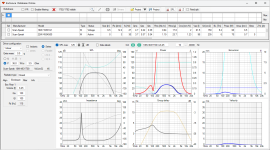
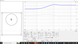
Just as a suggestion for something to pass the time in the evenings, fire up VituixCad go to Tools/ enclosure and from the list of drivers select your nice driver.
Then select infinite baffle for box type and check the auto align box I think you need a Q of 0.9 for your 6 litre box. in the crossover tab you can set say your wanted High Pass filter of 200Hz and your Low pass of 2.5 - 3.0Khz. which gives a nice simulated result. you can increase the power towards the blue limit line which I think suggests you can hit 111dB for the thermal limit. Now we need to consider you may need 6db or so to deal with the diffraction loss which takes us down to 105dB is that going to be enough for you?
See the attached.
It can be made to work well but you will not see the spl you were hoping for I think.
Attachments
Thank you Ray 🌹.It can be made to work well but you will not see the spl you were hoping for I think.
I´ve realize that my goal must have that "compromise" regarding to SPL.
And stilll wonder if i can bypass it, at least a little 🤔
If i integrate the mid so 30% of the midrange box goes in to the bigger 15 inch Dayton 390ho cabinette?
So the mid will have some more surface on the lower half.
VituixCad is a real good advanced program, and i have only learn 15-20% of it.
You will learn more & more during the rest of your life , and it make you wiser 😉
Regards John
Dont understand much, but interesting!See the attached
Attachments
For developing the speaker I would recommend less smoothing so you better know the real behaviour. You will need a gated measurement for tweeter and midrange without room interaction to do a good crossover.Don´t understand your suggestion?, can you please explain as i was a carrot
Some new mesaurement from 1 m
Hi Jawen,
I am still learning about VituixCad myself and have a fair way to go yet, it does seem capable of handling all of our capabilities we just need to understand to use all of its functionality. Within that there are user guides for REW, ARTA and Clio if I remember correctly. Have a look at those I go back to them when I get stuck and sometimes have to re read and re trace my steps if something doesn't work the first time.
at post 54 you can take that information and safe it/export it and the subsequently use that diffraction data to modify the enclosure response. NB I may have to go over this point.
Post 55 you moved the speaker outside of the box hence the funny response, but if you dont try you will never learn. 🙂
The diffraction loss feature is useful as you can see how you can lessen baffle step especially once you have a big baffle area or you are using a small tweeter. Offsetting the tweeter from the microphone position can produce some ripples and peaks.
Trying to learn REW a little better, and have read some about gated mesaurement.For developing the speaker I would recommend less smoothing so you better know the real behaviour. You will need a gated measurement for tweeter and midrange without room interaction to do a good crossover.
A newbi question?
Is this last mesaurement okey regarding room reflections?
The impulse look´s like this, and are the settings correkt?
Regards John
Attachments
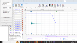

Zoom into the x axis to have around 10 ms of total length, the you will see first reflections!this scale
Usual values are: 1 ms left window (to avoid unnecessary wiggles at low response) and 4-8 ms right window
- Home
- Loudspeakers
- Multi-Way
- Maximize a Scanspeak 18M/4631 T00 Revelator midrange for a 3 way