Matti was blocked because PIM was too controversial for the AES. He told me this, himself.
Jan L. Bob has been a strong critic of Matti for decades, so it would be inappropriate for us to do a paper together.
Jan L. Bob has been a strong critic of Matti for decades, so it would be inappropriate for us to do a paper together.
ThermalTrak
To Bob Cordell,
Apologies that I referred to you as Bob Holmdel in my post #747.
In your post #738 you say: "More recently, ThermalTrak output transistors were introduced by OnSemi. By incorporating a sensing diode right on the header for the output transistor die, far better thermal tracking is available for use in setting up the class AB bias in the output stage. In my view, the availability of these transistors is nearly a game-changer."
This is interesting news. Did you see measering reports and schematics of amplifiers using these devices?
JanL
P.S. Can you explain how to incorporate a quote in a post.
PMA said:Makes sense. We are still unable to explain sound differences only by degree of FB, OL corner and SR. Just hints, not sufficient conditions.
And as Stereophile has proved after testing the Halcro amplifiers, you can have your cake and eat it too with lots and lots of feedback 😉
regards
Trev
JanL,
I really like your approach, immediately posing some relevant questions in the right direction.
The ability to detect small time differences (a couple of uS, probably much smaller) is essential for the main task, localization. Time and phase errors, reflections, represent a muddy, exhausting sound field.
I really like your approach, immediately posing some relevant questions in the right direction.
I cannot point at anything worth a mention.So I after those 37 years, what have been the key research results in audio?
Hearing has been subject to highly intensive, continuous research since the eighteenth century, so there`s certainly no lack of knowledge here.1. My first question is about the state of the art of the knowledge how our ears do function.
That´s another insightful observation of Otala. It is harder for the ear to live with the time related distortions than with the amplitude distortions.does it carefully ‘measure’ where the signal crosses the zero line
The ability to detect small time differences (a couple of uS, probably much smaller) is essential for the main task, localization. Time and phase errors, reflections, represent a muddy, exhausting sound field.
Now I`m thinking about the ear`s way of creating and suppressing harmonics, which is explored as well and should be taken into consideration. The question rather is, how to achieve such a spectrum with solid state devices. Linear tubes naturally produce something similar in single-ended mode, no global feedback applied. Especially bipolars have a propensity to produce high order harmonic and intermodulation products.2. If the answer on 1 is positive, in the sense that we know enough of the ear/brain mechanisms, have their been attempts to translate these to specs. of audio power amplifiers?
Jan,
I`ll try to give you an answer later (you won´t like it anyway).
Missing gain/bandwidth = no relationship between the input and output/high dynamic impedance = high distortion.
I`ll try to give you an answer later (you won´t like it anyway).
Missing gain/bandwidth = no relationship between the input and output/high dynamic impedance = high distortion.
Re: ThermalTrak
Here are comments on these TRs:
http://www.diyaudio.com/forums/showthread.php?s=&threadid=71534
Jan Lohstroh said:
This is interesting news. Did you see measering reports and schematics of amplifiers using these devices?
Here are comments on these TRs:
http://www.diyaudio.com/forums/showthread.php?s=&threadid=71534
Re: ThermalTrak
First you find on the page the message that you'd like to reply to, and that you'd like to quote. At the end of the message, bottom right corner, it will say "Quote" and to the right of it there is a little white box, which you click on to get the check mark in it. Then you scroll to the bottom of the page and click on the "post reply" button. You'll get the dialog in which you can edit your reply. The message that you wanted quoted will be seen in the dialog.
Jan Lohstroh said:
P.S. Can you explain how to incorporate a quote in a post.
First you find on the page the message that you'd like to reply to, and that you'd like to quote. At the end of the message, bottom right corner, it will say "Quote" and to the right of it there is a little white box, which you click on to get the check mark in it. Then you scroll to the bottom of the page and click on the "post reply" button. You'll get the dialog in which you can edit your reply. The message that you wanted quoted will be seen in the dialog.
Or you can just "Copy" the part you want to quote then when you write your response click on the "quote" button , a small window opens, and you can "paste" the quote in the window and edit it a bit , then click "OK"
It is not good form to quote an entire post
It is not good form to quote an entire post
Trevor White said:
And as Stereophile has proved after testing the Halcro amplifiers, you can have your cake and eat it too with lots and lots of feedback 😉
regards
Trev
Yes, for example.
BTW - you are in Adelaide - interesting 😉
Re: Tribute to Matti
Hi Jan,
John and I have disagreed on many things over the years and have a different view of history, so it would not be possible for us to write a paper together.
Matti did receive quite a bit of criticism over the years for some of the conclusions that he drew in his work. However, he was never blocked from presenting apapers at the AES or publishing in the Journal. All of the material he submitted went through the usual peer review process and was never reviewed by less than three reviewers. I was and still am on the JAES Review Board and knew Pat McDonald, the JAES Editor, very well at the time. I know from personal interactions that she bent over backwards to be fair to Matti.
Cheers,
Bob
Jan Lohstroh said:To Bob Holmdel and John Curl,
Thanks for your reactions on my post #730 and for reporting that a lot has happened the last 40 years and that a lot of distortion phenomena are better understood and can be measured. Apparently some classes of circuitry are effective in producing almost distortion-free drivers.
I guess the first publication of Matti was: Otala, M.: Transient distortion in transistorized
audio power amplifiers. IEEE Trans. AU-18 no. 3, 1970, pp 234-239.
As this thread is a tribute to Matti Otala, may I suggest that the two of you write together an overview article with a title like: “40 years of understanding distortion in audio power amplifiers, a tribute to Matti Otala”, in which you can mention what, in your opinion, was correct what Matti and others said, and what not. You could then also refer to my 8 questions from post #730 and indicate what is needed to bring this profession further to a higher level of objective understanding.
I can offer to proof-read your article.
Cheers,
Jan Lohstroh
P.S. It is new to me that Matti was blocked by AES in the 80's. Why was that? I guess by now AES would enjoy the article I propose you to write.
Hi Jan,
John and I have disagreed on many things over the years and have a different view of history, so it would not be possible for us to write a paper together.
Matti did receive quite a bit of criticism over the years for some of the conclusions that he drew in his work. However, he was never blocked from presenting apapers at the AES or publishing in the Journal. All of the material he submitted went through the usual peer review process and was never reviewed by less than three reviewers. I was and still am on the JAES Review Board and knew Pat McDonald, the JAES Editor, very well at the time. I know from personal interactions that she bent over backwards to be fair to Matti.
Cheers,
Bob
Re: ThermalTrak
Hi Jan,
Just check the little quote box in the lower right corner of the post that you wish to quore. Then scroll down and hit the post button.
There have been a couple of threads here on this forum where the ThermalTrak devices were delved into quite deeply. There is an app note from OnSemi on using them, but it is not the best approach. Among others here, I have done many measurements on the devices.
I also understand that Doug Self incorporated a chapter on ThermalTrak devices in the new Fifth Edition of his amplifier handbook, and that it includes some of the material discussed here. He was a participant in some of those threads.
The ThermalTrak transistors are a 5-pin device that incorporate an electrically-isolated tracking diode on the same header as the power transistor die. The power transistor is made with OnSemi's Perforated Emitter technology, which is largely a variant of the Ring Emitter approach, and yields very good ft and SOA.
As far as commercial examples, Charles Hansen of Ayre uses them in his MX R amplifier.
Cheers,
Bob
Jan Lohstroh said:To Bob Cordell,
Apologies that I referred to you as Bob Holmdel in my post #747.
In your post #738 you say: "More recently, ThermalTrak output transistors were introduced by OnSemi. By incorporating a sensing diode right on the header for the output transistor die, far better thermal tracking is available for use in setting up the class AB bias in the output stage. In my view, the availability of these transistors is nearly a game-changer."
This is interesting news. Did you see measering reports and schematics of amplifiers using these devices?
JanL
P.S. Can you explain how to incorporate a quote in a post.
Hi Jan,
Just check the little quote box in the lower right corner of the post that you wish to quore. Then scroll down and hit the post button.
There have been a couple of threads here on this forum where the ThermalTrak devices were delved into quite deeply. There is an app note from OnSemi on using them, but it is not the best approach. Among others here, I have done many measurements on the devices.
I also understand that Doug Self incorporated a chapter on ThermalTrak devices in the new Fifth Edition of his amplifier handbook, and that it includes some of the material discussed here. He was a participant in some of those threads.
The ThermalTrak transistors are a 5-pin device that incorporate an electrically-isolated tracking diode on the same header as the power transistor die. The power transistor is made with OnSemi's Perforated Emitter technology, which is largely a variant of the Ring Emitter approach, and yields very good ft and SOA.
As far as commercial examples, Charles Hansen of Ayre uses them in his MX R amplifier.
Cheers,
Bob
PMA said:Obviously, the TIM is still an issue :
Hi PMA,
Neat picture. Looks like some crossover distortion on that 5532 op amp.
What value of DIM does it measure by Otala's method using a spectrum analyzer?
Similarly, what value of THD-20 does it measure when looking at harmonics out to 200 kHz?
Thanks,
Bob
The reality is: Pat McDonald told Matti that the JAES was a 'Journal of Record' and that his paper could not be put into the JAES. He told this to me, himself. We all abandoned the JAES by this time, for much the same reasons. Of course, Pat was just the 'messenger'. Dr. Lipshitz and his crew ran things below the surface, in the 1980's.
Now, how close was I to the AES? Well, I was asked if I wanted to be president of the AES, by one of the presidents of the AES, in the late 70's. Is that close enough? I politely declined, because I did not have the organizational support around me, at the time, to make it happen.
I did serve as San Francisco Bay Area Chairman alternately for about 10 years, and attended AES staff meetings on occasion along with Walt Jung, who was an AES governor at the time. I was a full member of the AES for more than 40 years, starting in 1966.
I think the 100KHz+ fc 1st order filtered sq wave is unreasonable for an audio amp test:
even Earthworks - who make a point of "high bandwidth" electronics only offer one 50KHz recording mic - most of their recording mics are 25-30KHz and I'd expect all mics to have 2nd order roll-off
http://www.earthworksaudio.com/3.html
SACD requires a high order analog filter at 50KHz
anyone know the relative ratio of 88/96 vs 178/192 source being released on Video or DVD-A ?
no phono cart is going to track that edge at anything like the test amplitues
I don't know how good the sim model is but the real world 5532/4 definitely has slower pull down capability - as can be seen on the bench with a scope as a feedthru zero only on one side in a DAC I/V with feedback C if you're trying for sq wave response - it is clearly improved by "Class A" ccs bias
Bob Cordell said:Neat picture. Looks like some crossover distortion on that 5532 op amp.
What value of DIM does it measure by Otala's method using a spectrum analyzer?
Similarly, what value of THD-20 does it measure when looking at harmonics out to 200 kHz?
It would be also interesting to find out what NE5532 model was used in that simulation. The only NE5532/NE5534 spice model I have ever seen is coming from TI and is one of those stupid behavioural macromodels, completely improper for any THD, TIM, DIM and any other three letter acronym simulations. In fact, the model is only a degenerated diff pair with resistive loads, everything else are synthetic voltage controlled voltage/current sources feeding the output and the common mode, and a 50ohm resistor to simulate the OL output impedance.
How was the crossover distortion simulated using such a model is one of those deep mysteries

* NE5534 OPERATIONAL AMPLIFIER "MACROMODEL" SUBCIRCUIT
* CREATED USING PARTS RELEASE 4.01 ON 04/10/89 AT 12:41
* (REV N/A) SUPPLY VOLTAGE: +/-15V
* CONNECTIONS: NON-INVERTING INPUT
* | INVERTING INPUT
* | | POSITIVE POWER SUPPLY
* | | | NEGATIVE POWER SUPPLY
* | | | | OUTPUT
* | | | | | COMPENSATION
* | | | | | / \
.SUBCKT NE5534 1 2 3 4 5 6 7
*
C1 11 12 7.703E-12
DC 5 53 DX
DE 54 5 DX
DLP 90 91 DX
DLN 92 90 DX
DP 4 3 DX
EGND 99 0 POLY(2) (3,0) (4,0) 0 .5 .5
FB 7 99 POLY(5) VB VC VE VLP VLN 0 2.893E6 -3E6 3E6 3E6 -3E6
GA 6 0 11 12 1.382E-3
GCM 0 6 10 99 13.82E-9
IEE 10 4 DC 133.0E-6
HLIM 90 0 VLIM 1K
Q1 11 2 13 QX
Q2 12 1 14 QX
R2 6 9 100.0E3
RC1 3 11 723.3
RC2 3 12 723.3
RE1 13 10 329
RE2 14 10 329
REE 10 99 1.504E6
RO1 8 5 50
RO2 7 99 25
RP 3 4 7.757E3
VB 9 0 DC 0
VC 3 53 DC 2.700
VE 54 4 DC 2.700
VLIM 7 8 DC 0
VLP 91 0 DC 38
VLN 0 92 DC 38
.MODEL DX D(IS=800.0E-18)
.MODEL QX NPN(IS=800.0E-18 BF=132)
.ENDS
jcx said:
SACD requires a high order analog filter at 50KHz
Yes it does. But it is not any brickwall. Usually 3rd order. If you measured analog output of SACD players, you would find waves up to 100kHz with quite high amplitude, that's the nature of the DSD noise.
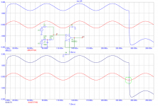
Regarding my 5532 tim image, someone might like kindly check the method, if it corresponds to that used by Otala and Curl. I mean a possible mix of linear and non-linear distortion (input BW limited square is subtracted from the wave that passed thru the opamp....)
PMA said:Regarding my 5532 tim image, someone might like kindly check the method, if it corresponds to that used by Otala and Curl. I mean a possible mix of linear and non-linear distortion (input BW limited square is subtracted from the wave that passed thru the opamp....)
Someone did and is telling me that the author simulated the response of a degenerated (329ohm) long tail pair (133uA ideal current source), modeled with Spice default npn devices, with resistive loads (723.3ohm), output loaded with a 7.7pF cap.
What has this to do with the real NE5532 opamp, crossover distortions, etc... only the author knows. In someone's else opinion, the author just delivered an example of the limited slew rate impact, available since the 60's in any analog design textbook. Which is exactly what Bob and others told here and elsewhere ad nauseam: this kind of effects have nothing to do with negative feedback and open loop bandwidth.
- Home
- Amplifiers
- Solid State
- Matti Otala - An Amplifier Milestone. Dead or Alive