I used to match power tubes in an amplifier by measuring the tube operating temperature. It takes a large lot of tubes, but same tube dissipation with same operating bias point and same tube gain is matched to me.
Not sure of your whole procedure, but offhand sounds like a bad idea as you have multiple sources of heat dissipation including heaters in an IDH power tube.

Indeed. And the tubes are in a different position so cooling will be different too.
Even the way of measuring the tube temperature is very inaccurate (where and how to measure).
Not a sensib;le way to match tubes.
Jan
Even the way of measuring the tube temperature is very inaccurate (where and how to measure).
Not a sensib;le way to match tubes.
Jan
I was testing Sylvania 7C5 Mil Spec that had the 6V6G plate. 6V6G tubes were expensive. Tested all in same socket thus no variance as you suggest.
So? What about the other issues? You say 'I tested ...".
How did you measure the temp? Equipment, method, position, repeatability?
Results?
Or is this just an idea? Nothing wrong with that - in fact it's better to discuss idea before investing and finding out it doesn't work.
Jan
How did you measure the temp? Equipment, method, position, repeatability?
Results?
Or is this just an idea? Nothing wrong with that - in fact it's better to discuss idea before investing and finding out it doesn't work.
Jan
The temperature at any point in time is just the balancing item which drops out as a result of heat generation minus heat dissipation and nothing more than that. You can make it what you want it to be by changing the cooling side of the equation. What a filament heater is doing is not a proxy for where the operating point might be at.
kind regards
Marek
kind regards
Marek
The tube temperature rise above ambient depends on the dissipated heat Ia x Vak, plus the heater generated heat. The cooling depends on the momentary ambient temp, local air flow, time, position of the two tubes relative to the environment etc etc. Your measurements of temperature depends on a lot of uncontrolled factors too.
There is no usefull connection between operating point and the temp you measure.
If nevertheless you can make a strong case for it, let me know and I will call the Nobel Committee for you ;-)
As an aside, given the almost non-existing info you give, I suspect you have not done an actual measurement.
As noted, it's fine to bounce ideas off of other. You can only learn.
Jan
I did measure the temperature. The parameters you mention have no application here. Tube measured in same socket in constant temperature environment.
That's right - you are adding up plate dissipation, filament, how gassy a tube might be, reflective getter, glass thickness, air currents, ambient room temperature and condensing that down to a single number when it could have been more easily defined with the voltages across a few components.
So after you have "matched them", you'll be taking ONE of the tubes and plugging it into a different socket, containing a different anode load resistor and a different cathode resistor, where it may be a slightly different cooling environment and still declaring yourself pleased with the result?
Why not just put a bias servo across it and be done?
kind regards
Marek
Think it through! Tube A has 20mA Ia and 200V AK, tube B has 22mA Ia and 182Vak.
Widely different bias point, yet the same anode dissipation and heat generation.
Apart from the issues of getting a repeatable and accurate measurement.
We're here to help to further your understanding. Digging in wont get you forward.
Jan
Widely different bias point, yet the same anode dissipation and heat generation.
Apart from the issues of getting a repeatable and accurate measurement.
We're here to help to further your understanding. Digging in wont get you forward.
Jan
Wrong again! NO tubes have anode resistors. They are in the circuit if the designer puts them there.
Readers here in the know will understand that depending on context anode resistor can also be impedance, an inductor, a transformer, what have you.
Only newbees would grasp the straw of semantics to try to save their point which has already been shown to be BS.
Good luck with your matching.
Jan
Readers here in the know will understand that depending on context anode resistor can also be impedance, an inductor, a transformer, what have you.
Only newbees would grasp the straw of semantics to try to save their point which has already been shown to be BS.
Good luck with your matching.
Jan
No you are wrong again. Power tubes never use an anode resistor. I did not state a tube has an internal anode resistor. No power tubes have an internal anode resistors. I will not reply to your posts now.
This doesn't work. I have quads of tubes all regulated to exactly 50ma via lm317 and the temperatures are all over the place. Even one tube has 100 degrees plus variance depending where you point ir temp.
100s of degrees difference with same bias and voltage? You mixing NOS and used tubes? Some of your tubes are barely operating and others maxed out. In fact, impossible on same construction tubes that are NOS. I point temperature gun at top of tube.
Last edited:
I am not saying measuring temperature replaces actual voltage and current measurements of new tubes. I just tried it.
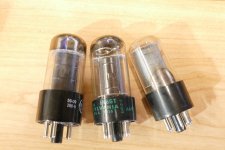
A large in difference in measured temperature is possible in different tubes that are running at exactly the same amount of total dissipation, especially when measuring from the top. You are attempting to measure the IR radiation from an "emissive body through glass of unknown transmissivity with a varying amount of gettering on the inside. I grabbed three random 6V6 types from my tube box selecting three tubes from different sources. All three have different plate structure, size and shape. Two are black and one is grey. The emissivity will vary with plate coating, and thickness.100s of degrees difference with same bias and voltage? You mixing NOS and used tubes? Some of your tubes are barely operating and others maxed out. In fact, impossible on same construction tubes that are NOS. I point temperature gun at top of tube.
Let's just assume that you have a large quantity of 7C5's and they are all the same. Are they all built exactly the same inside the plate? The point of highest thermal (IR) radiation is from the center of the broad side of the plate and a perfectly made tube should measure the same on either side. Virtually NONE of them will measure the same temperature even when biased up to identical levels of power dissipation. Few will measure the same from side to side since they were likely hand assembled many years ago and banged around a bit since then. Some of the old RCA tubes with black plates have obvious issues with the coating since there are light and dark spots and even a few silver areas in some tubes.
The heater wires were hand stuffed into the cathodes. They do not all protrude from the top equally, so measuring the top of the tube with an IR gun will see varying levels of heater heat. Try measuring the tubes from different directions with only the heater powered. Adjust your heater voltage for exactly the same power if you want, then look for the place to get the most consistent measurements after the tubes have had considerable time to heat up.
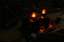
I do not attempt to match tubes by temperature. I use the IR gun, and my eyes in a dark room with the air circulation turned off to find the tubes that do the best job shedding heat WITHOUT developing hot spots on the plate. Concentrically made tubes like the 6AQ5 are the worst. They are rated for 12 watts od plate dissipation though very few can handle 10 watts without some redness on the plate somewhere. Some are so bad that a red spot will appear in the middle of one side at 8 watts or so. the plate is so close to the glass that there is not much power capability between red spot and hole in the glass.
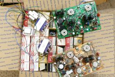
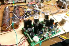
I recently revisited a nearly 20 year old experiment with some 6AV5GA tubes. In order to get consistent results, I got out a box full of tubes and rigged up a test setup with an UNSET board. I then tested a bunch of tubes to pick a few that would dissipate 20+ watts with even heating on both sides and no hot spots. All were tested at identical heater and screen grid voltage. The screen current at 20 watts (spec is 11) of plate dissipation was checked for outliers (I found one tube that sucked too much current compared to the others, so it went into the trash). The grid voltage to achieve 20 watts was recorded for each tube and matched pairs were made by selecting two tubes with identical internal construction with the closest grid voltages. Tubes like the 6AV5GA and the 6V6GT had long production runs with many changes, and the brand name on the tube does NOT indicate who actually made it. Two identical Sylvanias that were actually made by Sylvania were selected and used for audio testing.
Attachments
A 7C5 filaments were the same with none protruding from the top. Plus what tolerance? 1/8 watts? Does not contribute to tube temperature variances. All tubes are identical construction.
- Home
- Amplifiers
- Tubes / Valves
- Matching tubes by Operating Temperature