Not quite what I meant............
Andrew, the correction factor, the 10 ohm x 10 string, compared to 100 ohm then factor would be X, and the correction factor is X/10 for each 10 ohm resistor?..............
I'll work through a hypothetical example, using 10 off 10r, 1% in series and add a 100r 0.01% in series.
Set my CCS to 19mAdc. set my DMM to 199.9mVdc
the 100r measures Vdrop = 189.8mVdc the group of 10off 10r measures Vdrop = 188.2mVdc
We can calculate the current in the string from the 100r assuming it is still in calibration. I=V/R = 189.8mVdc/100r = 18.98mAdc
The group of 10off 10r must have a combined resistance of R=V/I = 188.2mVdc/18.98mAdc = 9r9157 or about 10r -0.843%
each 10r is on average 0.843% low.
You can also measure each 10r Vdrop and calculate each 10r
If all the readings (from the previous test) were the same, then you know each reading is +-1/2 a Least Significant Digit (LSD) which on a 199.9mVdc the LSD is 0.1mVdc and half that is 0.05mVdc
That's an error window of 0.05/188.2 = +-0.027%
Add on the reference resistor tolerance of +-0.01% to get 0.037%. Thus you are matching your same reading resistors to a tolerance of +-0.037% call it +-0.04%
That's not bad for buying one low tolerance resistor and a +-0.2% DMM
If you need a very accurate RATIO, then read up on a Hamon Divider. The standard three resistors gives 9:1 ratio for a 1/10th voltage reading.
A 4resistor Hamon gives 16:1 and 5resistors gives 25:1
A Hamon Divider built into one side of a Wheatstone Bridge is a good tool to have on the shelf.
Comparison is a very powerful tool for us amateurs who don't have calibrated instruments, nor calibrated references.
Last edited:
@Chris, My HP3457A came without a front panel fuse assembly.
AND
When I opened it up, the internal fuse assembly that connects to the main board was also missing. I've not been able to find the correct replacement. In the A.M. a call to Keysight.
@Andrew,
Thanks very much for explaining this. And now some of the power supplies that I've acquired actually make more sense to me. Being able to set both voltage and current. I'll have to go back through the manauls and read up on them along with the Hamon Divider.
Cheers,
Just noticed that in the example the DMM should be set to 1.999Vdc to read the Vdrop across a 100r passing 19mAdc.
Hi Sync,
That's annoying. Someone sold you a parts "donor" meter. Your only way to fix it might be to buy another donor 3457A. Not a great prospect.
Andrew, no, that should be 1.900 volts across a 100R00 resistor. 🙂
-Chris
That's annoying. Someone sold you a parts "donor" meter. Your only way to fix it might be to buy another donor 3457A. Not a great prospect.
Andrew, no, that should be 1.900 volts across a 100R00 resistor. 🙂
-Chris
I noticed that my earlier post said set the DMM to 199.9mVdc. On re-reading I realised I should have said set the DMM to 1.999mVdc. That's what I thought I said in post 163.
Last edited:
Further clarification here.
We've got the Constant Current Source set to 19 mAdc. I set the Vdc source to read on the DMM 1.999mVdc. Then when I apply this voltage source to the 100ohm resistor and measure the voltage drop across it.
1.999mV/100ohm = 20x10^-6 or 20 uA. Calc wouldn't go down that low.
Chris, Thank you for offering to take the HP3457A off my hands. Yeah, that parts unit 🙁. Fortunately Keysight has the two parts required and are on their way to me. Those, a Battery and 4 capacitors are all I need to keep it running, I hope....
Cheers,
Hi Sync,
That's really good news on the 3457A. I'm glad you got it sorted out so you can use it.
Hi Andrew,
If you are passing 1.9000mA through a 100R000000 resistor (let's make it dead on accurate), your meter will read 0.190000 volts assuming zero error. We aren't compensating for the burden of the voltmeter. Meters typically have scales like 1.9 V, but will read 1.999 volts before they overrange. If you have a 3 3/4 digit meter, it will read 3.999 before it overranges. They might call the former a 2 volt range, or 4 volt range for the latter. To generate that current in your string by measuring across the 100R resistor, you would set the voltage source to read 0.190 volts on your meter, or in the case of an HP 3457, you would read 190.000 mVDC. Using an HP 34401A you would read 190.0000 mVDC, but you'd want to be calculating your error budget here. In any event, you would be setting the options in these meters for a long AC time constant and averaging many readings (these meters do that internally) as well as the gate time to average the 60 cycle AC to zero (they should come up this way).
-Chris
Edit: I used those two meters as an example because Sync has them.
Thanks Chris,
Both you and Andrew explained that well. Even though I have those meters, my questions also pertain to use in the field, not just on the bench. The field has a range of areas that can't be reached and are "beyond the bench".
We don't bring a a lab or bench meter to the field.
That is why we have the fluke meters, with the nice yellow protective cover. Learned a lot, thank you.
Cheers,
I'm thinking of building this just getting a parts list together. Question on the wattage of resistors 1/4 of 1/2 watt fo those?
Hi reddish75,
I used 1/2W resistors for the collector and base as I recall. It's more important to get the 0.1% resistors than a high wattage. The current setting resistors were all 1/4W, most 5%.
The capacitors are approximate, you can use whatever you have as long as they fit properly.
The header strips must come from a proper supplier. I tried ones from Ebay and they really don't work. I threw them out due to difficulties with inserting transistor leads.
-Chris
Thanks Chris,
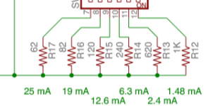
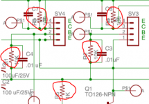
Which values were settled on for the collector and base resistors, from the schematic i noticed 100r for collector and 10k for base but from posted pics i see some examples using different? when you say current setting resistors you mean these (please see pic) These dont have to be 0.1% just the collector and bias resistors (please see pic 2)
Which values were settled on for the collector and base resistors, from the schematic i noticed 100r for collector and 10k for base but from posted pics i see some examples using different? when you say current setting resistors you mean these (please see pic) These dont have to be 0.1% just the collector and bias resistors (please see pic 2)
Attachments
Hi reddish75,
Differing resistor values can be used, but consideration to how your instruments will operate at those voltages need to be figured out first. For example, I use HP 34401A meters and could use 1R0 collector loads, but most people wouldn't be able to use the jig effectively. If you have the specs for your meter, figure out the possible error at the voltages you expect to measure. That alone can answer what values to use.
-Chris
I picked the values to have a minimal voltage drop that most meters could show, so 100R0 for the collector resistors. If 1R0 was used, the math would be simpler, but most meters would either be wildly inaccurate or wouldn't show more than 1 decimal place. Same thing, wildly inaccurate. The same thought process was used for the base resistors in case you wanted to measure base current. From that you could figure out transistor beta under those conditions.Which values were settled on for the collector and base resistors, from the schematic i noticed 100r for collector and 10k for base but from posted pics i see some examples using different?
Differing resistor values can be used, but consideration to how your instruments will operate at those voltages need to be figured out first. For example, I use HP 34401A meters and could use 1R0 collector loads, but most people wouldn't be able to use the jig effectively. If you have the specs for your meter, figure out the possible error at the voltages you expect to measure. That alone can answer what values to use.
Correct. You could use 1% resistors here if they are cheap enough. Many can be had for $0.15 each. Dale resistors would run about $0.83 each. They wouldn't break the bank. Just whatever you do use, do not use junk parts and carbon film are okay here.when you say current setting resistors you mean these (please see pic) These dont have to be 0.1% just the collector and bias resistors (please see pic 2)
Attached Thumbnails
-Chris
I like the "peak" boxes for measuring transistors.
It lets you connect any pin you like to any wire and it sorts itself out.
The only downside is when measuring power transistors it only puts a few mA through them which is a useless test.
It lets you connect any pin you like to any wire and it sorts itself out.
The only downside is when measuring power transistors it only puts a few mA through them which is a useless test.
I`ve tested the Peak transistor checker. It is useless for leakage since you need to measure uA, not mA. Otherwise it can be useful to figure out what leads are which. In the end, because there is no control over the temperature of the transistor, it`s only good for presorting transistors for a final and proper matching. It is no worse than any other beta checker in that regard.
-Chris
-Chris
I found that with power transistors the gain would be very high at mA where as at normal operating currents "amps" if would be much lower.
Hi Nigel,
I use a heat sink for 4 output transistors at once. Bring them to the same temperature and measure beta and match. It is effective, but really slow going. Again, the peak would be good for pre-sorting the parts before hitting this step. Close matching of power devices is even slower than signal transistors, but if you need crazy good matches, it`s the only way. One example is repairing a Counterpoint amplifier where the mosfets really do have to be very, very close. The yield on 50 devices is disheartening, better if you only need pairs. There's three days of your life you can put to better use. Yields are far better when you are using bipolar transistors with looser requirements. Still, these matches are far better than you can get with any normal beta testing.
-Chris
How do you make a complimentary transistor matcher?
By measuring two/pair at a time.
THx-RNMarsh
By measuring two/pair at a time.
THx-RNMarsh
Hi RIchard,
I've been trying to think of a way of doing that easily. I keep coming around to the fact that one has to track the other. Probably will design one using op amps and other linear electronics.
At the moment I have the emitters commoned and the bases common but through resistors. Collectors each have precision matched resistor loads. I could use a servo to set each emitter current the same and then calculate Beta from that. It would be nice to have a heater with servo to keep the heat sink at the same temperature. Then I would run the outputs at the expected bias current.
I think output transistor matching is effective near the crossover point. At high currents the emitter resistors enforce current charing as those voltages swamp the emitter - base voltages. That's exactly what we want, a clean changeover from one polarity to the other. This makes it viable to rely on 1 watt THD tests and looking at the crossover notches in the residuals of a THD meter. (looks like I'm keeping the HP-339A).
-Chris
- Home
- Design & Build
- Equipment & Tools
- Matching transistors & measuring the results