DSP is certainly more flexible, but for us analog only people, its hard to be content with having an extra step of AD/DA in the signal path. I'd try to go analog active with the xover, but that also has similar limitations as a passive xover and can add more noise than a DSP setup.
OK, I'm obviously lost in the weeds when looking at those ( post#4 ) predictions because what they predict don't seem to come close to matching the real off-axis FR measurements made by either Kevin or Pierre on their actual Yuichi//TAD horns.AFAIK, the red line is 44.4 degrees off axis. He is showing the effects both on and off axis.
( Are they supposed to represent ) Off-axis frequency response to the horn bell or is it instead representing a sharp off-axis turn ( expansion ) within the initial flare rate?? ( IOW; 44.4 degrees of throat diffraction before the horn bell ?? )
As I've said, I don't get the purported significance behind that post ( I think Google Translate barely makes cryptic ESL palatable )
🙂
Last edited:
Exactly my point. 👍Then for a hyperbolic-exponential horn:
Flare rate will increase with horn length if T < 1 (Cosh horn).
Those are a diffraction disaster. My recommendation would be to stay away.a cool company that makes wood conical horns
Most, but not all.Really interesting points being made here. Just throwing this out ... do all radial horns have square entrances? I know the Yuichi A290 and many multicell horns have square entrances, and some multicells have what amounts to an internal adapter to transition from circular to square in the horn itself.
Some (few) have a round entrance, and then the rectangular cross-section has an inner fillet with a radius that is initially = that of the throat.
E.g., see the (very expensive but very well made) Japanese radial horns by GT Sound
The JBL 2420 is an older AlNiCo magnet version of the 2426...new dual diaphragm 2420
No, you can make it very smooth:Really interesting points being made here. Just throwing this out ... do all radial horns have square entrances? I know the Yuichi A290 and many multicell horns have square entrances, and some multicells have what amounts to an internal adapter to transition from circular to square in the horn itself.
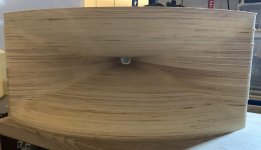
But the traditional rectangular throat is easier to design but leaves the adapter as a missing link:

The JBL 2420 is an older AlNiCo magnet version of the 2426...
Yes and no. There is a new version I should have written DA2420
Rob 🙂
https://www.audioheritage.org/vbull...gm-Drivers-2430-2415-2420&p=421194#post421194
I must say this is interesting, and thanks to Pano for starting it. As a newcomer to horns & drivers I have found both confusing and wondered if one could just select any horn and driver (given the correct relationship of size 1", 1,4", 2"). As a woodworker I've thought of making my own horns but realized that it really was a shot in the dark as to what would work and have resisted.
Following up on David who shared equations relevant to the topic, let me introduce a couple more.In the case of an exponential or hyperbolic-exponential (hypex) horn, m is normally used as the symbol for the flare constant. T is normally used as the symbol for the hyperbolic-exponential horn flare parameter.
The cross-sectional area at distance x from the throat of a hyperbolic-exponential horn is given by:
Sx = S1 * (-(1 + T) * Exp(m * x) - (1 - T) / Exp(m * x)) ^ 2 / 4
There is only one flare parameter value that satisfies a set of Sx, S1, x, and F12, and it is given by
T = ( sqrt(Sx/S1) - cosh(m * x) ) / sinh(m * x)
where:
m = flare constant = 2 * Pi * F12 / c
Alas the hypex equation contains a transcendantal function of F12 meaning that F12 can not be isolated in a closed form expression and must be searched iteratively. F12 and T are tied together. Find or set one and the other is a given.
Following up on Pano's question on angular matching, matching just the flare is choosing a driver that has an exit half angle close to that of the entrance of the adapter (halfAngle(0)), which is given by
halfAngle(x) = atan( [ sqrt(Sx+eps / pi) - sqrt(Sx / pi) ] / eps)
where
x is distance and set to 0 for finding the angle at the entrance of the driver
eps is some arbitrary but very small distance
Sx+eps and Sx are the hypex areas calculated at distance x+eps and x using the equation given by David.
As an example, taking F12 = 320 Hz, T=0.7 and a 1.4" adapter entrance, the half angle there is 4.16 degrees. A driver having a 10 degree exit (5 degrees half angle) would fit well.
Turning to the exit end of the adapter, provided that the horn and adapter are both hypex with the same F12 and T, then their flare angles at the mating point must by definition match perfectly - as must their areas. This is if they are both round, otherwise the angle is not constant around the periphery.
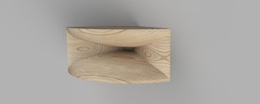
The missing link.But the traditional rectangular throat is easier to design but leaves the adapter as a missing link:
This is well put! How does one select a driver and an adapter to fit a rectangular entrance horn?
Given the knowledge, computers and 3D printers we now have, I think there is an opportunity to design very good adapters. Better ones than could have been designed back then. Hey, our adapters can even be tailored to fit specific driver and horn pairs.
Looking into this, I find that there is a minimum difference in surface area between the adapter entrance and exit that allows designing a throat expansion profile that is close to optimal - especially if one wants to crossover low. Starting with a 1.5 or 1.4 inch exit driver gives plenty of length to meet all the constraints that I cited above (size, angle, flare constant, wavefront shaping). A 2 inch driver does not leave much room to adapt the waveform for a TH4001 or Yuichi A290 horn for instance. In the pro world I guess this is less of an issue as they tend to crossover higher.
OK, thanks for the example. Running the numbers in Hornresp, I can see the angle being about 4.17 degrees, which would be a near match for the half angle of a 10 degree exit driver. By about 9.6cm into this horn, the angle has now doubled. With the same size horn but T=0.8 we are closer to a half angle of 5 degrees at the entrance. But is it the angle we want to match, or is it expansion rate?As an example, taking F12 = 320 Hz, T=0.7 and a 1.4" adapter entrance, the half angle there is 4.16 degrees. A driver having a 10 degree exit (5 degrees half angle) would fit well.
Wouldnt it be cool if there was a visualization - like this one - of what happens when there's an angular mismatch between the horn and adapter?

Also how the "jets" of gas coming out of the phase plug converge within the adapter. That'd be neat to see.
Also how the "jets" of gas coming out of the phase plug converge within the adapter. That'd be neat to see.
Yes, if customizing your horn, then T=0.8 would fit this driver better, and probably sound close to the T=0.7. Not sure what you mean by driver expansion rate? The driver's "T" is infinity if its throat is conical, which I understand they typically are.OK, thanks for the example. Running the numbers in Hornresp, I can see the angle being about 4.17 degrees, which would be a near match for the half angle of a 10 degree exit driver. By about 9.6cm into this horn, the angle has now doubled. With the same size horn but T=0.8 we are closer to a half angle of 5 degrees at the entrance. But is it the angle we want to match, or is it expansion rate?
If selecting the driver for a given T=0.7 horn, then I would personally consider 5 degrees "close enough" and not loose sleep over this. (We're doing this for fun!). Alternatively I would be satisfied by a throat-less driver of the same exit size - as many pointed out.
We're neglecting another factor at play here: the small conical driver exit throat makes the wavefront less flat and a bit more spherical (I think: am I right?) I assume this is negligible and not used by horn designers, but does anyone know?
Our Canadian friend, Joseph Crowe, has discovered that 18Sound has been doing some very odd things with their published frequency response and polar graphs:
(Crowe's multitone measurement of IM distortion is quite rigorous and exposes much more IM distortion than the usual 2nd and 3rd-harmonic graphs that are published. Few others are using this technique to examine differences between compression drivers.)
(Crowe's multitone measurement of IM distortion is quite rigorous and exposes much more IM distortion than the usual 2nd and 3rd-harmonic graphs that are published. Few others are using this technique to examine differences between compression drivers.)
Last edited:
By comparison, the value-priced ($200) SB Audience 1.4" exit compression driver is surprisingly good ... and does not behave like most titanium-diaphragm drivers, with first breakup raised to 17 kHz, and very fast transient decay. (For those new to the discussion, this is close to beryllium-level performance at one-tenth the price.)
Last edited:
has discovered that 18Sound has been doing some very odd things with their published frequency response and polar graphs:
That's discouraging and IME ( observationally ) seems to be a bit of an outlier ( experience wise for others and their 18Sound gear ).
Usually, 18Sound delivers the goods in spades.
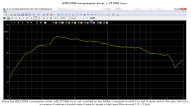
Here are Troels Gravesen's measurements of the 18Sound NSD1095N on the 18 Sound XT1086 waveguide ( it doesn't really get much better than this for a raw response on a smallish horn );
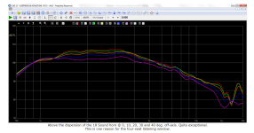
🙂
Last edited:
- Home
- Loudspeakers
- Multi-Way
- Matching horns to compression drivers, a discussion

