Hi,
Well I hope you looked at some of the pcb layouts or bought a kit by now and are building your HPA. In the layouts and kits you can get a sense of what the Wattage for R's is. Basically, All can be 1/4w except those in the output stage - they should be 1-2W resistors..... the 4.7 and 18 Ohm.
To lower the gain, you can increase R5 to maybe 2K.
Increasing OPS bias beyond what is used in original isn't needed. The distortion is already extreamly low and you might have to change output devices.
THx- Richard
Richard, what's up with wearing that dumb-looking cowboy hat in your latest avatar??😀
Did you recently visit Texas?
You look like you're really p_$$ed and ready to gun down some other cowboy.
Just having a little fun with you Mr. Marsh, so don't take it seriously.
Now...let's bust out the moonshine and soldering iron and build something!🙂
Did you recently visit Texas?
You look like you're really p_$$ed and ready to gun down some other cowboy.
Just having a little fun with you Mr. Marsh, so don't take it seriously.
Now...let's bust out the moonshine and soldering iron and build something!🙂
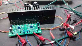
A couple of folks have asked about boards. Restating, they are $3 and have two amplifiers. Shipping varies all over the world. Here is a picture of what they look like:
Hi jackinnj, I sent you a PM; looking forward to building this! I've never been a headphone guy, but lots of DIY turntables, phono stages & the like. Do you have any recommendations for power supply?
Hi jackinnj, I sent you a PM; looking forward to building this! I've never been a headphone guy, but lots of DIY turntables, phono stages & the like. Do you have any recommendations for power supply?
I used a Lambda brick for the first one. Another has an Amveco torroid and CRC filter.
You can use a wallwart and DC-DC converter with a low noise post-regulator I've used Murata and Meanwell, but thesedual output devices should work, and cost ~$16.
https://www.recom-power.com/pdf/Econoline/RS6.pdf
I think Jan's "Simpleswitcher" isn't quite up to the task as it will only source 150mA.
Richard, what's up with wearing that dumb-looking cowboy hat in your latest avatar??😀
Did you recently visit Texas?
You look like you're really p_$$ed and ready to gun down some other cowboy.
Just having a little fun with you Mr. Marsh, so don't take it seriously.
Now...let's bust out the moonshine and soldering iron and build something!🙂
I don't know what possessed me. Goofy mood, I guess.
-Richard
Do you have any recommendations for power supply?
I used this one with great success:
Positive and Negative +/- 1.25~37V DC Adjustable Voltage Regulator Module | eBay
I used the devices from your article. JFET's usually matched to 100uA Idss, 2N's matched for vbe or hfe. the output transistors matched similarly -- MJE's are slightly quieter than 2SD/2SB but the latter have higher gain and show less distortion.
Transistors/diodes for 2 channels $27.50, complete set of parts (no power supply) $54.00. PM if interested.
I have 2 complimentary transistor matchers -- very twitchy.
FWIW, I think I mentioned way back in this thread that even with randomly selected devices the performance is really excellent.
PM Sent. With all the rave reviews I am in for the full kit if still available.
Thanks... Chris
Gilding the lily ---
i think, since I found the THD lowered with higher DC ps voltage, other higher voltage rated output transistors should be used at +/- 22-24vdc at 250mA minimum per channel. 300mA or more should be enough.
The suggested alternative transistors seem fine for use with higher voltage PS. be sure that the pS cap voltage is high enough.
What I found specifically, is the 3H drops more than 2H as PS voltage is increased. Just going from 15v to 22-24 vdc dropped the 3H about 15dB.
The reason for this drop in HD is because the FET device C's continue to go down as PS voltage goes up. These C's are quit non-linear. Another factor is the topology -- the push-pull complimentary input makes C of gate-drain cancel at input with input connected together. So we dont need to cascode with the spec'ed jFET devices. .
Dont get too excited - we are talking about levels already below -110--120dB to -135dB. The residual mismatch in C's can be trimmed further 😱
You can add some small C with a trimmer cap to one side to balance the C values which then cancel. Or, since the C's are voltage dependent, a drop in the - Vs of 3 diodes in series with neg PS will change the C enough to make + and - equal and null.
But, just run at higher voltage will do the most good for the least effort. Be sure heat and voltage rating on caps and transistors etc are adequate. I added small heat-sinks to the second stage (Av).
Enjoy.
THx-Rnmarsh
Last edited:
More importantly, What happened to the cowboy hat?
🙂 Its spring and time for a change. I havent seen sun in so long -- I am looking for my dark glasses now.
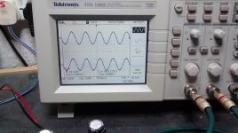
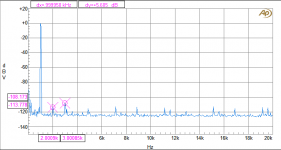
...... and on a secondary issue .... what most people can expect from this HPA is - 110dbV. Without the heroics:


-Richard
It doesn't change much at all at any freq or load or level.

45 Ohm load. 20KHz.
2v would just double 20KHz thd to .002%
THx-RNMarsh
45 Ohm load. 20KHz.
2v would just double 20KHz thd to .002%
THx-RNMarsh
Last edited:
The boards and matched parts arrived today. Thank you Richard and Jack!
I will try this at 18V rails.
Do the 2SK170 & 2SJ74 need to be BL or GR as preference?
If BL there is a nice choice of matched ranges from 6mA - 10mA, where in the range would be good?
Rich 🙂
I will try this at 18V rails.
Do the 2SK170 & 2SJ74 need to be BL or GR as preference?
If BL there is a nice choice of matched ranges from 6mA - 10mA, where in the range would be good?
Rich 🙂
The -170/-74 have much higher capacitance and might have higher distortion because of it. Cascoding would be recommended for lowest distortion with those devices.
THx-RNMarsh
THx-RNMarsh
All good Richard, I got a bit excited but calmed down and re-read the thread and see the 170&74 are optional.
Finally found some time to fire up the headphone amplifier.
Firstly my thanks to Richard, Jan and Jack for their respective parts in bringing this amplifier build together.
On the input I opted for the 2n5460 & 2n5457 jfets in the sot23 smd variant as they are easily available from Farnell and cheap to buy in x50 batches of each type to give a good selection range for matching using a Peak DCA75 with the smd transistor adaptor. The output transistors are MJE200G/MJE210G sets also from Farnell.
The psu was the one from eBay upped in an earlier post in this thread, thanks to the op. It's set at +/- 15vdc output for this amplifier.
The board assembly went well, fired up without any problems, test heatsink eventually gets luke warm. After setting the mid points to uV values off zero point a prolonged on test period shows almost perfect stability.
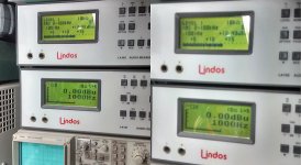
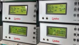
Connected 47R loads to the outputs and started measuring, which did not produce expected results as follows:
Gain is good at around 12.4dB
THD values @ 1kHz input @ 0dB level L=0.0169% & R=0.0173%
THD values @ 10kHz input @ 0dB level L=0.0163% & R=0.0220%
Comments/suggestions?
Firstly my thanks to Richard, Jan and Jack for their respective parts in bringing this amplifier build together.
On the input I opted for the 2n5460 & 2n5457 jfets in the sot23 smd variant as they are easily available from Farnell and cheap to buy in x50 batches of each type to give a good selection range for matching using a Peak DCA75 with the smd transistor adaptor. The output transistors are MJE200G/MJE210G sets also from Farnell.
The psu was the one from eBay upped in an earlier post in this thread, thanks to the op. It's set at +/- 15vdc output for this amplifier.
The board assembly went well, fired up without any problems, test heatsink eventually gets luke warm. After setting the mid points to uV values off zero point a prolonged on test period shows almost perfect stability.
Connected 47R loads to the outputs and started measuring, which did not produce expected results as follows:
Gain is good at around 12.4dB
THD values @ 1kHz input @ 0dB level L=0.0169% & R=0.0173%
THD values @ 10kHz input @ 0dB level L=0.0163% & R=0.0220%
Comments/suggestions?
Attachments
Finally found some time to fire up the headphone amplifier.
On the input I opted for the 2n5460 & 2n5457 jfets in the sot23 smd variant as they are easily available from Farnell and cheap to buy in x50 batches of each type to give a good selection range for matching using a Peak DCA75 with the smd transistor adaptor. The output transistors are MJE200G/MJE210G sets also from Farnell.
Did you match the outptut transistors, and the 2N5087/88?
Both Dr. Marsh and I obtain THD% an order of magnitude better.Connected 47R loads to the outputs and started measuring, which did not produce expected results as follows:
Gain is good at around 12.4dB
THD values @ 1kHz input @ 0dB level L=0.0169% & R=0.0173%
THD values @ 10kHz input @ 0dB level L=0.0163% & R=0.0220%
Comments/suggestions?
FFT is always nice. It will tell us a bit about what's going on with your power supply. Second, do your THD% analyzers allow for 400 Hz High pass and 22kHz or 80kHz low pass function.
The 2SB649/2SD669 transistors have somewhat higher HFE than the On-Semi's MJE's (albeit at somewhat higher noise.)
Was there any effect upon THD% by adjusting the second trimmer potentiometer?
Attachments
Thank you for your prompt reply...
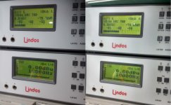
The Lindos analyser has a default 22kHz low pass setting for the common distortion measuring sequences. The 400Hz high pass is a switchable option. Its THD+N resolution is 0.005% which is plenty enough to show if this project is heading in the right direction.
Only in as much as ten of each of the four types allowed. I was under the impression that the jfet matching was the most crucial so need to see where this design is going before buying larger quantities of the other transistors.Did you match the outptut transistors, and the 2N5087/88?
Indeed and my expectation in the first pass was not that of a honed setup but, tbh, did not expect that low a result.Both Dr. Marsh and I obtain THD% an order of magnitude better.
I'll dig out the QA400 tomorrow and see what it shows.FFT is always nice. It will tell us a bit about what's going on with your power supply. Second, do your THD% analyzers allow for 400 Hz High pass and 22kHz or 80kHz low pass function.
The Lindos analyser has a default 22kHz low pass setting for the common distortion measuring sequences. The 400Hz high pass is a switchable option. Its THD+N resolution is 0.005% which is plenty enough to show if this project is heading in the right direction.
Never used these MJE's before so have no frame of reference.The 2SB649/2SD669 transistors have somewhat higher HFE than the On-Semi's MJE's (albeit at somewhat higher noise.)
Indeed there was, left channel THD reading was achieved with the pot at the end of its wiper run whilst the right channel at the same THD figure looks like its got some more to go before it hits the end of its wiper range.Was there any effect upon THD% by adjusting the second trimmer potentiometer?
- Home
- Amplifiers
- Headphone Systems
- Marsh headphone amp from Linear Audio