I have some problem with the DC offset at amp output. The problem is due to small - 3-4mV voltage at the output of my source. The question is - how to resolve it better: by decoupling caps like : ????? ?????????? - WIMA - MKS2B046801M00JSSD - CAP, FILM, PET, 6.8UF, 50V, RAD or 1 Pair 2pcs of Mundorf Mcap Supreme Capacitors 2 600 1400V All Values | eBay, or to build a simple DC servo with some fet input opamps, like TL082 ?
Personally I would address the issue at the source and leave the amp alone.
The source still on the warranty, and I don't wont to void it. And I don't think that 3-4mV at output is valuable reason to open RMA request. Even if RMA request will be accepted, the shipping of my DAC to factory, will cost much more than pair of caps, or servo...
Last edited:
First see if you can null/zero out the source dc on its' output. Maybe the source can be servo'ed. Or try a REL MultiCap on output of source.
THx-RNMarsh
THx-RNMarsh
Hello Richard,
I can't to touch the source.
I looked at caps you suggested. I need 6.8-10uF cap, to use with the 10KOhm input. PPMFX is claimed as ultimate series. The dissipation factor is:
< 0.05% 1.0 - 10.0 uf @ 1kHz @ 25 degress C
tol: 10%
Counterpart from Mundorf - Mcap supreme:
Loss factor: tan ∂ = 0.0002@1 kHz; 0.0001@10 kHz
tol: 2%
Jantzen Superior Z-Cap MKP looks similar to MCap from Mundorf.
Tolerance value is non critical here, but Mcap far better in terms of looses.. Or I missed something ?
Now the DC servo. I tried to simulate you amp circuit with DC servo added, and noticed kind of improvement in THD floor. The amp benefits from low THD if output DC offset is so small as possible. DC servo doing here perfect job.
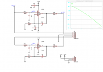
Attachments
Last edited:
I am not sure but could be true. However the distortion in your sim is much higher than measured on my HPA.
Use the PPMFX cap. to block dc coming in from your source. Compare with and without a cap on input. Then compare against your servo.
THx-RNMarsh
Use the PPMFX cap. to block dc coming in from your source. Compare with and without a cap on input. Then compare against your servo.
THx-RNMarsh
Of course, simulation isn't precise, especially while software optimized mostly for MCU. But even such simulation can to show a general behaviour, and to give some start point.
I tried to measure HPA using Creative Zx soundcard, and it show about 0.009-0.005% (-81 -88dB) THD. The soundcard + Arta are not the ethalon of the precision also.
I waiting for 'DIY Audio Analyzer with AK5397 and AK4490' or that Onix ADC became available.
I tried to measure HPA using Creative Zx soundcard, and it show about 0.009-0.005% (-81 -88dB) THD. The soundcard + Arta are not the ethalon of the precision also.
I waiting for 'DIY Audio Analyzer with AK5397 and AK4490' or that Onix ADC became available.
You probably wont be able to measure the distortion with anything but the best instrumentation and care in layout and shielding when testing; If you use the transistors I used. But the prposed DIY analyzer should get you easily to -100dB accurately (.001%).
Tell me more about the sound you have now, then with cap and then with servo.
Thx - Richard
Tell me more about the sound you have now, then with cap and then with servo.
Thx - Richard
Wow Wow Wow... I need some time 🙂 I'm not living in either USA EU or Japan.
There is no Hi Fi electronic components stores here. So capacitors I should to order from you country. Then PCB for DC servo I need to order from East, because PCB produced in my country will cost just more than the whole amplifier.
The PPMFX caps I found here Michael Percy Audio Ordering Information 8uF X 200V costs $16.25 , for PCB I'll contact a factory in Hong Kong.
The HPA sounds now very good to my ears, very accurate and natural. There is tight and deep bass, detailed, airy, and smooth treble. The treble are similar to treble produced by my hybrid HPA - just very pleasant, and absolutely non fatiguing.
Well, I assembled a servo at kind of breadboard. First of all it defeated that voltage offset.
While amp with input shorted to ground was drifting +-3...5mV, with source connected and volume on max it was about 20mV, now, it 0-0.4mV regardless to what's going on the input.
The servo works better if it ground connected to the star ground point just between the regulators.
With 100K resistors on input and 50K at output of the servo, the LF roll off begins somewhere about 2Hz -0.1dB, 0.8Hz -0.2dB.
I didn't noticed either noticeable changes in the sound. Probably hi end became more transparent. But it can be a my subjective bias.
Thank you for you input jackinnj,
I used TL082 due to I own some of them. I'll try to order OP297, and to put them to the business🙂 Is the OP97 is single version of OP297 ?
I used TL082 due to I own some of them. I'll try to order OP297, and to put them to the business🙂 Is the OP97 is single version of OP297 ?
I wonder how many months of work Dr Marsh put into the design and development of a headphone amp that is direct coupled and DC stable without a servo, and now seeing people adding a servo to it....
yes. I suspect the same p/n for transistors were not used. The ones I used were also operated at their zero TC bias point and does not drift.
When you force an unbalanced amp to balance by servo you often get higher distortion.... balanced for DC isnt always the same as balanced for AC.
However, I would not bother with servo with the small offset being talked about.
A misuse of a dc-servo has been to zero out an unmatched/unbalanced stage.... I developed the servo concept primarily for reducing dc drift. With closely matched devices and the ones selected and operated as I did.... offset and balance is not an issue and distortion (as measured) is extremely low.
THx-RNMarsh
Last edited:
RNMarsh 24th January 2013 07:01 PM
Hyper tuning --
Now if you want to hyper tune the amp, and if you can measure the harmonic distortion way down low ---- You can add another trim in place of R10... a value of 500 ohm should work well. Or, you can jumper in a 2K pot across the existing R10 and adjust for distortion null and replace pot with a bridging R value of the trim pot value. I found some more reduction in thd this way when under load (<100 Ohms).
Here is my proceedure to try if you have the thd equipment: Apply load R to the amp.... using the dc offset pot, trim to minimum thd. You will then have a dc offset. Then, using the pot at R10, readjust for zero dc offset. Maybe a little back and forth and you will have the lowest possible thd... even beyond matching. In my case changing R10 value by only 40 ohms improved the performance under heavy loads. So, use a multi-turn trimming pot. How much improvement depends on how well you matched all your transistors. The matching of the jFET provided by jackinnj is even tighter than i did... so i cant say how much better you can get under load, but its what i do.
Yupp, carefully trimming R10 and adjusting P1 nulls both distortion and DC offset. You have to be patient, going back and forth from one to the other. I adjusted mine for the load of the Sennheiser HD650's.
the small signal transistors are the same. The power transistors are 2SB649AC 2SD669AC.I suspect the same p/n for transistors were not used.
Do I have to change these to MJE210G 200G ? The problem is that obtaining MJE2XXG is subject to import from US only, and farnell asks $0.64 per transistor if I buying a bunch of 25+ units.
And I found strange behaviour: while voltage across CE of Q1 and Q2 are equal at one channel, the second channel shows 0.5V imbalance, and the output of that channel is always 2.9-3.2mV(even with the servo connected) while another channel 0.1-0.4mV ...
Looks like something was not matched carefully enough ?
Another question - do I have to use separate radiator for each channel ?
I'm just trying to get my amp running properly. I'm not looking for the way to pervert , or to "improve" excellent circuit of Dr Marsh.I wonder how many months of work Dr Marsh put into the design and development of a headphone amp
Good to know you used the same input devices. You should not have a drift issue.
I used separate heat sink on each output transistor.
You might want to match devices closer on the one channel with greater offset.
-RNM
I used separate heat sink on each output transistor.
You might want to match devices closer on the one channel with greater offset.
-RNM
Last edited:
2N5210 (NPN) seems to be a little easier to match to the 2N5087 (PNP).
With respect to output devices, I attained lower THD% with the 649/669, vs the MJE200/210 but YMMV.
With respect to output devices, I attained lower THD% with the 649/669, vs the MJE200/210 but YMMV.
I agree... somewhere later I mentioned that the 5210 and 5087 gave a higher yield for matching.
Did you run same currents and R's in OPS thru the 649/669? If so, I'll try that.
THx-RNMarsh
Did you run same currents and R's in OPS thru the 649/669? If so, I'll try that.
THx-RNMarsh
- Home
- Amplifiers
- Headphone Systems
- Marsh headphone amp from Linear Audio