Just did the measurements again. Used a Multimeter and left the amps powered on for 3-4 seconds only, since I don't have a heatsink mounted.
R16/R17: 410mV over 4R7 ~ 87mA
R13/R14: 1.05V over 18R ~ 58mA
R9/R10: 10V over 220R ~ 45mA
D1-D3: 2.57V
Both channels measure the same within a couple millivolts.
Rails:
15.44V @ 0.37A
-14.8V @ 0.37A
According to simulation (no exact models though), the current through R9/R10 seems a little high, which likely biases the output stage higher. Do you think this might be due to the 2SJ103/2SK246?
I don't think there's any problem in the circuit, just the discrepancy between the calculated Ibias from the voltage across the Re's (about 160-170mA for two channels) and the indication on the psu meter IF you measured across R11, R12. THAT is the voltage that determines the bias current. Did you measure that?
jan
jan
Last edited:
Just did it: 640mV over 4R7...
... which is 136mA (if it is across a single 4.7 ohms); two channels is then 272mA. Getting closer....
Maybe you should put the transistors on a heat sink. Keeping them cooler will lower the bias current, and you probably get into the ballpark.
Or else check with Richard (he's a member here) if his '>200mA' includes 270mA or so... 😉
Jan
The transistors didn't get hot during the short measurement period, only a little warmer than room temperature. I'll report back how it behaves once it's heatsinked.
I hope Richard still follows this thread and chimes in 🙂.
I hope Richard still follows this thread and chimes in 🙂.
I just finished building this Marsh design and I can not get it to work properly. 😡
I'm trying to use it as preamp. instead of a headphone amp. I purchased both the board and semiconductors from the TechDIY store so I wouldn't have to fool around with matching transistors.
All the components are new and I checked and double-checked each component, except for the diodes, before soldering everything in place.
The only thing I changed was C1 and C2 to 470uF.
When I apply power(+-15V), all the output devices' heatsinks get nice and toasty in a couple of minutes and most importantly there's no smoke.
When I connect a DVM across the outputs, I get 0 volts on both channels even when switching to the 200mV setting...no offset at all. Turning the 1K trimmers either direction doesn't change anything. I have tried measuring the offset with the input shorted and not shorted, but I still get nada.
So I decide to connect it to an amplifier. A few seconds after I power it up, R12(4.7 ohm) starts smoking.
I quickly cut it off, disconnect the RCA's from the amplifier and put the amp back on my bench. After applying power R12 isn't smoking anymore. It now runs cool like all the other 1 watt resistors.
So for whatever reason...R12 only smokes when the output is plugged into an amplifier.😕
I have measurements across R11-R17 if someone here needs them for troubleshooting.
Output transistors are 2SB649AC and 2SD669AC instead of the MJE devices.
I'm not sure what's going on here, so any help would be GREATLY appreciated!
Thanks!
Did you measure your +-15V under load? Does any one of them drop significantly?
No short circuits at the heat sink or anywhere else?
Do you have a scope to look for oscillations?
No short circuits at the heat sink or anywhere else?
Do you have a scope to look for oscillations?
Did you measure your +-15V under load? Does any one of them drop significantly?
No short circuits at the heat sink or anywhere else?
Do you have a scope to look for oscillations?
The only things(RCA interconnects going to and from the board) I assumed as being good, turned out to be the problem.
Apparently they were shorting out the outputs and causing some of the emitter resistors to smoke when placed in certain positions or moved a certain way.
Even though they were new and not particularly cheap interconnects, it just goes to show you can not assume anything when working with electronics.
My Marsh amp is now working as it should and sounds great!🙂
Also, thanks to John at TechDIY for the nice PCB's and matched transistors.

... which is 136mA (if it is across a single 4.7 ohms); two channels is then 272mA. Getting closer....
Maybe you should put the transistors on a heat sink. Keeping them cooler will lower the bias current, and you probably get into the ballpark.
The amp is heatsinked now, but the rail current only drops to 0.35A from 0.37A. I ran it for about 10 minutes and all the TO92's got a little hot to the touch. Guess this is not normal 🙁.
Out of curiosity I shorted one of the three diodes, which resulted in a bias current of about 47mA instead of 136mA (rail current was lower, too). IMHO this looks like I'm either 40mA too high or too low 🙁.
I thought about replacing the three diodes with a single red LED. They measured 2.58V across, which is a little odd 0.86V per diode. Roughly 2.1V seems to be the better fit here. What scares me are the 10V across R9/R10 (220R in my case), which should mean something like 40mA through the diode string. Will that fry a single LED? 😕
Lasse, all the TO-92's on my board run warm, but not hot.
The output devices are a different story, even with heatsinks they run hot after several minutes of use.
If you need any measurements across any of the resistors, I'll be glad to measure my example and post them for you.
The output devices are a different story, even with heatsinks they run hot after several minutes of use.
If you need any measurements across any of the resistors, I'll be glad to measure my example and post them for you.
Thank you for your offer! What about your R9/R10 and the three diodes?
I opted to go with only two diodes now, but the voltage across R9/R10 is still 10V +- 10mV. Once I find the time I'll see if it works as expected and doesn't run overly hot anymore.
I opted to go with only two diodes now, but the voltage across R9/R10 is still 10V +- 10mV. Once I find the time I'll see if it works as expected and doesn't run overly hot anymore.
You could also bridge one diode with a resistor until you have the Iq you want. Leave the diode in for some thermal tracking.
Jan
Jan
Jan, thanks for the tip! I'll probably try it out, especially if it helps reducing distortion 😱...
The amp is running now for about half an hour and the TO92's are only warm and not hot. Looks fine.
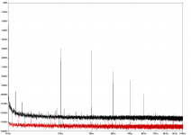
I did a first THD test, albeit without any load connected (sound card input only). Not sure whether this has any negative impact, but the values I measured surely leave something to be desired...
Generator was the soundcard itself, set to 1kHz and -12dBFS, which is 1VRMS. The loopback test measured 0.00018% THD and 0.0035% THD+N, see the red trace below.
With the amp in between and the volume pot turned down to compensate for the amp's gain, I now read 0.42% THD and THD+N, see the black trace.
I suppose this will look even worse with a load connected... To figure that out, I'm planning to build a Jack-adapter which permits to connect a headphone and a multimeter for offset adjustment at the same time to the output socket.
Up till now the 500R trimmer were only adjusted to measure 220R like R9/R10 via multimeter and the 1k trimmer used to null out offset. Do you think it's easily possible to get such bad results simply due to bad alignment?
EDIT: Just checked the other channel: It is even worse, reading 1.72% THD! (Graph scale is in dBV)
The amp is running now for about half an hour and the TO92's are only warm and not hot. Looks fine.
I did a first THD test, albeit without any load connected (sound card input only). Not sure whether this has any negative impact, but the values I measured surely leave something to be desired...
Generator was the soundcard itself, set to 1kHz and -12dBFS, which is 1VRMS. The loopback test measured 0.00018% THD and 0.0035% THD+N, see the red trace below.
With the amp in between and the volume pot turned down to compensate for the amp's gain, I now read 0.42% THD and THD+N, see the black trace.
I suppose this will look even worse with a load connected... To figure that out, I'm planning to build a Jack-adapter which permits to connect a headphone and a multimeter for offset adjustment at the same time to the output socket.
Up till now the 500R trimmer were only adjusted to measure 220R like R9/R10 via multimeter and the 1k trimmer used to null out offset. Do you think it's easily possible to get such bad results simply due to bad alignment?
EDIT: Just checked the other channel: It is even worse, reading 1.72% THD! (Graph scale is in dBV)
Attachments
Last edited:
I got it! 😎
After messing around with several resistors (which really is no fun at all on a tightly-packed, plated-through perfboard), I can finally say that 220R instead of 249R for R9/R10 was a bad decision 😱. My first thought was to use them 'cause I had them, and finally I forgot to order 249R, so I had to use them...
Well, I went with 470R instead now, which is just covered by the 500R trimmers' range. Together with 2k2 (instead of 3k3) for R2/R3, I arrived at the following values now:
103mA bias current
13,2mA through R9, so roughly 13mA through the diode string
3,1mA through R2
2,20V (instead of 2,56V!) for the diode strings
Looks fine to me, so far. Only downside is, I had to drop the rails by 2V, because +-12,5V at those currents is a little too much for a 2x12V 2x5VA toroid. Luckily I went with 2 LEDs in series to a Zener at the Adj-Pin of LM317/337 regulators, so I simply had to short them out.
After some warming-up I re-measured the THD, still without a proper load and prior to any fine-tuning except offset trimming. Values in parentheses are from the first measurement.
THD: 0.13% (0.42%)
k2: -60.83dBV (-49.70dBV)
k3: -61.63dBV (-52.06dBV)
k4: -112.75dBV (-74.61dBV)
k5: -102.94dBV (-84.45dBV)
k6: -124.23dBV (-99.66dBV)
Much better now. I have to admit though, that I skimped on the matching... I did not want to buy a big bunch of transistors, so I opted for twice as much and simply matched for Vbe. So I presume THD-wise there's not an awful lot more to gain, but at least the offset is well behaved.
Hi Lasse,
I have no experience with this myself so I can't comment on the THD, but my feeling is that it should be a bit better. Why not mail Dick Marsh, he'd be delighted to hear from you!
BTW Nice soundcard, what brand/type is that? Or did I already ask you?
Jan
I have no experience with this myself so I can't comment on the THD, but my feeling is that it should be a bit better. Why not mail Dick Marsh, he'd be delighted to hear from you!
BTW Nice soundcard, what brand/type is that? Or did I already ask you?
Jan
Why not mail Dick Marsh, he'd be delighted to hear from you!
Will do.
BTW Nice soundcard, what brand/type is that? Or did I already ask you?
No, you didden't 😀. It's an ESI Juli@.
You really have to use ASIO and dithering, because Windows Audio is limited to 16bit...
@preamp: You should be able to do much better than that. The P and N channel input JFETs may be way off their optimal Idss and gm. This is the result I obtained -- the matching of the output devices helps, but it isn't as important as getting a good match on the input devices:
An externally hosted image should be here but it was not working when we last tested it.
Jack, thanks for your suggestion. I'll match the remaining FETs with the circuit Richard suggests in his article and see if that helps.
Will do.
No, you didden't 😀. It's an ESI Juli@.
You really have to use ASIO and dithering, because Windows Audio is limited to 16bit...
Thanks. I wish I could find one as good as the Juli@ with a USB interface...
Jan Didden't do it. 😉
- Home
- Amplifiers
- Headphone Systems
- Marsh headphone amp from Linear Audio