Jack and DT, I looked the Bode-100 up... you boys are playing with some kit. Damn.
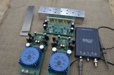
I have a new 25Mhz Picoscope. Better than nothing and more than that, it looks a very handy tool and a big thanks to MarkS for going out of his way to offer advice regarding USB scopes. Very much appreciated Mark.
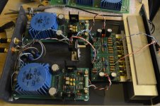
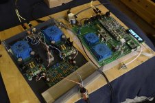
Everything is assembled and ready, in my effort to recycle and save a few pennies I have used Aluminium angle and box section as heatsink assembly. It may be inadequate so I will add some mass if necessary. Lets see if I can post some useful data.
Sync - you are looking around for supplies and may have seen my previous post, but I will be trying the Sulzer all in one supplies from ATL. They are set to around -/+18V altough one positive rail is just over 19V... I suspect my matching of 5.1V diodes could have been better on this side.
There is some component measurement/matching and fixed resistor value calculation involved with these, I will suggest to Alex that the circuit have trimmers to help dial in the output.
I have a new 25Mhz Picoscope. Better than nothing and more than that, it looks a very handy tool and a big thanks to MarkS for going out of his way to offer advice regarding USB scopes. Very much appreciated Mark.
Everything is assembled and ready, in my effort to recycle and save a few pennies I have used Aluminium angle and box section as heatsink assembly. It may be inadequate so I will add some mass if necessary. Lets see if I can post some useful data.
Sync - you are looking around for supplies and may have seen my previous post, but I will be trying the Sulzer all in one supplies from ATL. They are set to around -/+18V altough one positive rail is just over 19V... I suspect my matching of 5.1V diodes could have been better on this side.
There is some component measurement/matching and fixed resistor value calculation involved with these, I will suggest to Alex that the circuit have trimmers to help dial in the output.
Attachments

jackinnj,
Yes I did. The toy fund had a nice ROI.
DT
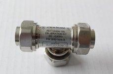
Get yourself a Pomona 1296 BNC-Male to binding post adapter, a 50 ohm 1206 or 0805 resistor and make an "OPEN-SHORT-LOAD" calibration adapter for the single port impedance measurements.
SMD resistor has very, very low inductance.
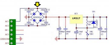
With that transformer and that circuit+PCB, you definitely will see very high Q, a/k/a very low zeta, ringing across the transformer secondary. Configure your scope's vertical amplifier for AC coupling (very important!), connect the ground clip, and attach the probe tip to the node marked with a yellow arrow below. Cowabunga, many ring a ding dings. You'll get an even cleaner, even prettier scope waveform if you use a handheld, battery powered scope that's not grounded. Connect the probes to measure across AC1 and AC2 (with AC coupling). Nice! The Fluke ScopeMeters are a mighty good line of handheld scopes, but I cheaped out and bought a low priced battery powered unit from China on FleaBay.... Signal A41-25-16 power transformers on the shelf, rectified they will put out about 24VDC. I will use these power transformers with the AudioWind regulators linked in a previous post. I am skipping using the Quasimodo snubber/zobel and come back if there is an issue.
And with twelve diodes on the board, very few people would decide to spend (12 x $1.10) to populate it with HEXFRED diodes, or (12 x $2.00) for Silicon Carbide diodes. Those aren't even the "best" {least ringing} diodes, but they are the ones that get recommended the most often on audio chat websites.
_
Attachments

Last edited:
I'm Jealous, that bode-100, looks sweet. Good Job.
For the time being, I've got to stick to gear in my "collection" as Demian calls it.
Mark, from where did this come from? Is there a table to which it refers?

I can across ranking of power supply regulator design with listening test from Linear Audio. By the way, I would encourage anyone to head on over to Linears Audio's web site where you can buy the discounted bookzene in groups of 4, 6, and 10. When they are gone, that's it. LINK
From John Walton's article where ranked 13 power supply regulators, (Table 7, p187) the top three are shown as:
Cheers,
Walton, J. (2012). A comparative overview of power supply regulator designs with listening tests. In J. Didden (Publisher/Editor), Linear Audio Vol. 4. (pp. 171-194). Linear Audio of Turnhout, Belgium.
For the time being, I've got to stick to gear in my "collection" as Demian calls it.
Mark, from where did this come from? Is there a table to which it refers?
I can across ranking of power supply regulator design with listening test from Linear Audio. By the way, I would encourage anyone to head on over to Linears Audio's web site where you can buy the discounted bookzene in groups of 4, 6, and 10. When they are gone, that's it. LINK
From John Walton's article where ranked 13 power supply regulators, (Table 7, p187) the top three are shown as:
- Jung/Didden
- Burson
- Sjostrom.
Cheers,
Walton, J. (2012). A comparative overview of power supply regulator designs with listening tests. In J. Didden (Publisher/Editor), Linear Audio Vol. 4. (pp. 171-194). Linear Audio of Turnhout, Belgium.
Last edited:
Jackinnj,
Thanks for the heads-up, I placed an order for a Pomona 1296 BNC-Male to binding post adapter.
Mark Johnson,
You talked me into it. I will hook up an oscilloscope to the AC connection to the Power Supply brick and observe what is going on AC wise. That matches your yellow arrow in your post, node S.
Node S will have all the AC junk; 120Hz switching buzz and transformer secondary / diode ringing.
I will also sample at the inlet of the LM317 pre-regulator. The smoothing capacitors will have removed much of 120Hz buzz and ~ 100K transformer / diode ring at this sampling point.
While I am at it I will also sample at the inlet of the second or final LT1963 regulator. I suspect that 120Hz buzz and 100K ring will both be below -100dBV at this point. Don’t know!
Thanks DT
You remove it because it's an unsightly wart, and because the cost of removal is so low. Even if the wart turns out to be completely benign, you remove it because you can.
Others have had this same wart and have reported huge improvements in health and well-being after removal. But you are not them and vice versa.
Others have had this same wart and have reported huge improvements in health and well-being after removal. But you are not them and vice versa.
Just a comment about ranking of the regulators. The performance of the super regulator is very dependent of the opamp and the pcb layout.
Hi P-A, I didn't know what the super regulator was, and it wasn't obvious until you mentioned it, then I had to look further. It's the "Sjostrorn Super Regulator".
So, if I understand you correctly, there were either 3 terminal regulators from the article or they were boards available to be made by DIYers.
Get yourself a Pomona 1296 BNC-Male to binding post adapter, a 50 ohm 1206 or 0805 resistor and make an "OPEN-SHORT-LOAD" calibration adapter for the single port impedance measurements.
SMD resistor has very, very low inductance.
Hi Jackinnj,
So how do these work? I mean I have some adapters 1296 BNC-Male to bindpost adapter...but how would I make a OSL type T from the BNC/Post?
I have no problem not spending the $460 to over $1K (USD) for them by DIYing it. Just wondering though.
Cheers,
Attachments
Last edited:
Walt has archived his articles:I'm blind and for some reason searchs didn't work.
Where is the link for the Jung-Didden Reg/PSU?
http://waltjung.org/PDFs/Improved_PN_Regs.pdf
More here:
References & Regulators | Walt's Blog 2014
Hello,
Back in post 1493 I spoke about using a Signal A-41-25-16 transformer to power a Audiowind A-270 regulator, turns out that transformer does not putout high enough voltage for the drop across the rectifiers, pre regulators, LM317 / LM337 and final, LT3015 / LT1963A, regulators.
Today I received a higher voltage version of the transformer Signal A-41-25-28, this transformer works out better.
330R resistors across both negative and positive outputs.
Line voltage 123VAC
Loaded transformer output 34.62 VAC
Voltage at input to pre-regulators after bridge rectifier and first smoothing capacitor -22.86VDC, +22.88VDC
Voltage at outputs -15.2VDC, +15.2VDC
Transformer 94.5 degrees F
Regulator heat sinks 91 degrees F
Tomorrow I will connect the oscilloscope and look for line frequency / harmonics and transformer ringing remnants at the first smoothing capacitor, then the pre regulators, lm317 LM337, plus the outputs of the, LT3015 LT1963A.
Thanks DT
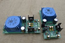
Richard - your amp sounds excellent. My HE-500's are loving it. Forgive me, my time is limited just now with house renovations going on so will get the scope to measure THD as soon as I figure out the software settings. I also forgot to buy output load resistors for testing, they are on their way.
As soon as it played music first time I just got on with listening. Three headphones here of different types: Focal Elear 80-ohm dynamics, HE500 planars and a pair of rare AKG K340 hybrid electrostats at 300 ohm impedance.
The AKG's are legendarily hard to drive to optimal levels and this amp needs the volume at full whack to get results but the heatsink still runs at very safe temps. I think his amp likes planars... the HE500 sound great.
Rails are around 19V. Offset is 0V. Everything worked first time, very easy build with Jack's supplied transistors. This amp is healthy.
Attachments
Last edited:
Hello,
Hooked up the Audiowind PS to the oscilloscope.
There was no hint of transformer / rectifier ringing. If you look at the center group of full bridge rectifiers on the drawing there is no place to isolate the rectifier without also having the first smoothing capacitor connected.
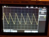
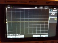
Adjusting the time scale to pick up rectifier buzz there is 400mV triangle 120Hz buzz at the first smoothing capacitor (first attached photo). At the regulator output the 120 buzz is reduced to the oscilloscope noise floor (second attached photo).
Adjusting the time scale to pick up transformer / rectifier ringing there was no ringing detected at the first smoothing capacitor or regulator output (third photo).
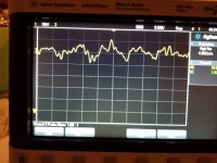
Adjusting the time scale to the high frequency end of the oscilloscope’s range there was a little wavy thing at near 1Ghz. This 1G thing was detected at both the first smoothing capacitor (fourth photo) and to a lesser extent at the regulator output.
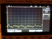
Counting the bumps on the trace and the ticks on the oscilloscope grid there is a ~ 7GHz little ripple riding the 1GHz wavy thing (fifth photo). That 7GHz ripple appears to be Oscilloscope artifact, with the probe ground clip attached to tip of the probe the ripple persists (no photo).
The photos are taken with my cell phone. I will sort out how to save screen shots to the computer for improved resolution.
The audio analyzer will a different view of the PS performance.
Then we connect the PS to the HPA
Thanks DT
Hooked up the Audiowind PS to the oscilloscope.
There was no hint of transformer / rectifier ringing. If you look at the center group of full bridge rectifiers on the drawing there is no place to isolate the rectifier without also having the first smoothing capacitor connected.
Adjusting the time scale to pick up rectifier buzz there is 400mV triangle 120Hz buzz at the first smoothing capacitor (first attached photo). At the regulator output the 120 buzz is reduced to the oscilloscope noise floor (second attached photo).
Adjusting the time scale to pick up transformer / rectifier ringing there was no ringing detected at the first smoothing capacitor or regulator output (third photo).
Adjusting the time scale to the high frequency end of the oscilloscope’s range there was a little wavy thing at near 1Ghz. This 1G thing was detected at both the first smoothing capacitor (fourth photo) and to a lesser extent at the regulator output.
Counting the bumps on the trace and the ticks on the oscilloscope grid there is a ~ 7GHz little ripple riding the 1GHz wavy thing (fifth photo). That 7GHz ripple appears to be Oscilloscope artifact, with the probe ground clip attached to tip of the probe the ripple persists (no photo).
The photos are taken with my cell phone. I will sort out how to save screen shots to the computer for improved resolution.
The audio analyzer will a different view of the PS performance.
Then we connect the PS to the HPA
Thanks DT
Attachments
-
 Low Frequency setting at smooting capacitor.jpg876.5 KB · Views: 370
 -
 Low Frequency setting at regulator output.jpg983.5 KB · Views: 336
 -
 no rining.jpg983.5 KB · Views: 325
 -
 High Frequency setting at smooting capacitor.jpg757.5 KB · Views: 98
 -
 High Frequency setting regulator output.jpg795.3 KB · Views: 109
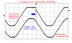
Here's what you should see when measuring the voltage across the secondary. A huge spike when the AC wave falls below (Vcap + Vdiode_fwd), i.e., when the rectifier cuts off. This spike stimulates 4-10 cycles of oscillation at a frequency between ~ 30 kHz and ~200 kHz, depending on the leakage inductance of the transformer. When you're successfully triggering on the spike-down, you can zoom in by increasing the horizontal sweep rate.
Yes yes the AC mains in my lab is distorted something awful (lower trace), with mooshed flat peaks and troughs instead of ideal perfect sinewaves. You might be surprised when viewing your own labs' mains waveshape.
If your intuition tells you "it oughta get worse, the more current I draw from the supply," you win a prize. The greater the output current, the harder the diode must work, and the harder it will "slam the door" when the diode cuts off.
_
Attachments
Last edited:
- Home
- Amplifiers
- Headphone Systems
- Marsh headphone amp from Linear Audio