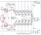
You are right. After replacing C212 470uF 10V capacitor on the OL-2 board, it does not trip.I suspect the elcos in the overload circuit.
The separate PCB containing this part is located a the back of the chassis.
Those elcos with a brown plastic encapsulation are of bad quality and have the tendency to explode after some time.
Hans
Hi Chansiukwing,
I am curious, did you make the change for the OL-2 board that Hans described in this topic? (p.17)
I suggest that you do it because it protects your amplifier and it is very easy modification.
I am curious, did you make the change for the OL-2 board that Hans described in this topic? (p.17)
I suggest that you do it because it protects your amplifier and it is very easy modification.
No, I just replace the ROE EK capacitors.Hi Chansiukwing,
I am curious, did you make the change for the OL-2 board that Hans described in this topic? (p.17)
I suggest that you do it because it protects your amplifier and it is very easy modification.
Hans,
I need again your help with my right amp. The problem is a bit similar than in my post #356.
One day I turned the amp on and I heard loud hum from the transformers(I think) and no sound from the right channel.
I have connected the 100R resistors in the VCC unregs and there is 85V drop in the resistors even if the pot R124 is completely open. Now I have only 4 pairs of output transistors connected and all the voltages over the 10ohm base resistors and the 0.22 resistors looks normal. This time when I short the WH.1 and WH.5 the voltage over the 100R resistors is only around 1V.
I can provide you more data...
Here are some data that you might be interested:
I have now 8 TO3 output transistors connected instead of all 12 pcs.
10ohm base resistors:
+(mV) -(mV)
30 18
29 18
30 18
31 19
0.22ohm emitter resistors:
+(mV) -(mV)
44 45
44 44
44 47
47 44
If you need any other data I will measure.
- voltage drop in the 100ohm resistors in the VCC unreg lines: 85V in both lines(pot R124 fully open).
- R50 = +0.8/-0.8(V)
- R45 = +1.49/1.53(V)
I have now 8 TO3 output transistors connected instead of all 12 pcs.
10ohm base resistors:
+(mV) -(mV)
30 18
29 18
30 18
31 19
0.22ohm emitter resistors:
+(mV) -(mV)
44 45
44 44
44 47
47 44
If you need any other data I will measure.
So, when shorting WH.1 to WH.5 there is almost no current flowing through the 100R resistors.
To be honest, I don´t know what R45 and R50 are, but anyhow, it seems that the problem must be something in the output stage but not in the 8 output transistors.
To start with, I would like to know the output voltage with the two 100R resistors still in place.
The next thing to be measured is how much current is flowing from WH.1 to WH.5 when replacing the short by you multimeter.
This should be between 16 and 18mA.
Hans
R45 and R50 are the resistors between the pos and neg predrivers in the output stage. I have been measiring those a lot in the past.
Output (LS) voltage is only a few mV if not zero. There is no current flowing from WH.1 to WH.5
Output (LS) voltage is only a few mV if not zero. There is no current flowing from WH.1 to WH.5
Zero volts in the output was when WHs were not shorted. I measured the with the WHs shorted and the output voltage is 13mV. The pot is working and no shorts in the transistors Q38 or Q50.
O.k. results so far.
The voltage amp seems to be working allright and so are your 8 output transistors.
Now the next step I would like you to do is to put a diode between WH.1 and WH.5 and measure the voltages over the two 100R resistors that you inserted.
When this still shows a very low current flow, add a second diode and meausure again.
Depending on the outcome we can take the next steps.
Hans
When you don't have enough diodes available you could also insert a resistor.
With 18mA, this should be something like 150R.
Hans
With 18mA, this should be something like 150R.
Hans
4 diodes and voltage still 1.3V over the 100R resistors. I assume that all the diodes have to be in the same way and that is what I have done. I have tried to change the bunch of diodes other way around but same result.
Of course should all diodes be placed in the same direction.
Did you remove the short between the WHs?
What is the voltage drop over the 4 diodes ?
Hans
Did you remove the short between the WHs?
What is the voltage drop over the 4 diodes ?
Hans
- Home
- Amplifiers
- Solid State
- Mark Levinson No23 repair help