Hans, these values look more logical and closer to the relative values in the positive part. At least the ones I measured around Q121/Q122.
Could be the problem at Q119/120 and/or Q124? In fact, nothing else left unchecked...
Tomorrow I plan to remove the board from heat sink to check what is going on underneath. A lot of work, but this issue with the unsoldered transistors made me doubtful.
In this way I can change also the small caps, which I don’t like in any case....
By the way, why this circuit has two Vreg outputs? One on the right and one on the left part.
Are they two different regulators or they are connected somewhere later? The right part goes to Voltage Gain board. The other?
Thebe,
I only have the two circuit diagrams for your amp that you made available, but all ML amps that I have come across were all based on the same family structure, including many diodes, darlingtons for current sources, the differential Vas and the same output current stages, etc, etc.
However your amp has a novelty that I haven’t come across before which is a dual differential Vas, quite interesting.
And yes, Vreg is not only used for the gain stage but also for the slow start circuit, the output current protection circuit and the heat sensing/dc output voltage protection.
Hans
P.s. I further leave it to Mooly because getting instructions from two directions is confusing.
Last edited:
Hi Mooly,
Sorry to interfere and with all respect for your attempts to find the error, I have the following remark.........................
No problem 🙂
It was all getting a bit frantic, we need to work more slowly and confirm all the results accurately. There were posts appearing in the time new replies were being typed and so it got difficult to keep track off.
My reasoning to track this one down is to start from the output and see where the 'loop' fails because those voltages from the first differential pair should be driving the output to the negative rail and of course that isn't happening.
I'll have more time later today hopefully 🙂
First step is to check out of circuit that R164 and R165 are good. You must do this first.
The reasoning is that if one of these is open then you will get exactly the fault you are experiencing.
The -53 and - 39 volts you see on R145 and R146 would also occur under this condition because the B-E junction of Q122 would be reverse biased and so act more like a Zener of around 6 to 8 volts at a guess.
It all fits your fault so lets check those resistors.
Attachments

Thebe,
I only have the two circuit diagrams for your amp that you made available, but all ML amps that I have come across were all based on the same family structure, including many diodes, darlingtons for current sources, the differential Vas and the same output current stages, etc, etc.
However your amp has a novelty that I haven’t come across before which is a dual differential Vas, quite interesting.
Sorry Hans, i forgot to send the diagram for the protection circuit yesterday. I will do it tomorrow - pls remind me if not.
Unfortunately today i have to travel, so no time even for testing.
First step is to check out of circuit that R164 and R165 are good. You must do this first.
The reasoning is that if one of these is open then you will get exactly the fault you are experiencing.
Hi Mooly, unfortunately i have no time today, although i 'm very curious - we have to postpone it for tomorrow.
I will check these resistors (R164/R165). However i have not noticed something strange on them (on circuit) and i can adjust this part according to ML recommendations (voltage drop on R170=2,1V)
Theo
Thebe,
I only have the two circuit diagrams for your amp that you made available, but all ML amps that I have come across were all based on the same family structure, including many diodes, darlingtons for current sources, the differential Vas and the same output current stages, etc, etc.
However your amp has a novelty that I haven’t come across before which is a dual differential Vas, quite interesting.
Well, here are the additional diagrams i've got, for the VSMB board (protection circuits, soft start, etc.)
Probably they help....
Theodore
Attachments
First step is to check out of circuit that R164 and R165 are good. You must do this first.
Hi Mooly,
i checked the resistors, they are OK.
R164=20K
R165=19,92K
I also checked the other two 'big' resistors:
R159=80K
R161=80,6K
But these two changing during the time. They are not stable. Could be a problem?
Another problem i have: i tried today to disassemble the big PCB from the heatsink to check what is going on underneath. It seems that the power transistors are very well 'glued' on the isolating material. Any idea how could i remove them?
Probably by heating them a while?
Theodore
Theodore
Theodore
They had to be checked to be sure 
No resistor should change at all as you measure it but the measurement must be out of circuit and you must have a good and stable connection to the resistor leads. Those two are an oddity and I can't see what they do tbh.
Lets look at this next...
Check that Q124 and Q125 are OK. There should be approx 1.1 to 1.2 volts across R163. These two transistors form a current source and if the current is low then you would get to little output volts.
Also check that C118, the 10n across the B-E of Q124 is OK and not leaky.
Another problem i have: i tried today to disassemble the big PCB from the heatsink to check what is going on underneath. It seems that the power transistors are very well 'glued' on the isolating material. Any idea how could i remove them?
Probably by heating them a while?
I doubt they would be glued. Old heatsink compound can appear like this if it has run hot for years. Maybe try and twist the device with pliers if you need to. Don't pry it off as that could put burrs on the metal.
Check that Q124 and Q125 are OK. There should be approx 1.1 to 1.2 volts across R163. These two transistors form a current source and if the current is low then you would get to little output volts.
Also check that C118, the 10n across the B-E of Q124 is OK and not leaky.
I can not check any of the small TO-92 transistors, cause their Base (middle pin) have a small isolating pipe.
Capacitors can not be checked as well (only the axial ones).
That's why i tried to remove the PCB.
Theodore
I doubt they would be glued. Old heatsink compound can appear like this if it has run hot for years. Maybe try and twist the device with pliers if you need to. Don't pry it off as that could put burrs on the metal.
This is what i meant... they are very old, so from the heat they have been 'glued' on isolating material.
Well, here are the additional diagrams i've got, for the VSMB board (protection circuits, soft start, etc.)
Probably they help....
Theodore
Theodore,
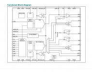
Your amplifier is software controlled, see image below.
All the (many) relays in your amp are driven by this device, controlling and sensing all vital functions.
First of all you should repair your power regulator, but if you are still having trouble with bias current, it is probably because this controller detects something that's out of range, or a relay that stopped working.
But chances are very great that everything is O.K. again after your power has been repaired.
Hans
Attachments
I can not check any of the small TO-92 transistors, cause their Base (middle pin) have a small isolating pipe.
Capacitors can not be checked as well (only the axial ones).
That's why i tried to remove the PCB.
Theodore
Can you not measure to other parts that connect to the part of interest, at least to see if anything is greatly amiss?
A first check is just to see what the voltage across R163 is. It should around 1.1 volts as mentioned earlier. If that is OK then its a fair bet that the stage is OK (providing R163 is OK in value).
I finally removed the board...
I have to say that i am very disappointed...!🙁
I found no problem till now....
I have to order some parts, mostly capacitors (to change just in case), but nothing obvious found! And for the moment i can not do any tests....
Hans, do you think that the problem can caused from the VSMB circuit?
I have to say that i am very disappointed...!🙁
I found no problem till now....
I have to order some parts, mostly capacitors (to change just in case), but nothing obvious found! And for the moment i can not do any tests....
Hans, do you think that the problem can caused from the VSMB circuit?
Can you not measure to other parts that connect to the part of interest, at least to see if anything is greatly amiss?
I can not see where the tracks go, it's dual layer board.
Assuming that the circuit diagram is correct, there is no way that the power regulator can be manipulated from outside.Hans, do you think that the problem can caused from the VSMB circuit?
So there’s definitely someting wrong on the power regulator board
Hans
I can not see where the tracks go, it's dual layer board.
OK 🙂 I know you have to work on it in a way that you feel comfortable with.
Assuming that the circuit diagram is correct, there is no way that the power regulator can be manipulated from outside.
So there’s definitely someting wrong on the power regulator board
Hans
OK, clear.
Under these circumstances, if I power only the regulator (V pre-reg +/-), is it possible to damage the rest circuit?
I want to exclude any external reasons and simplify the whole process as much as possible.
I see no reason why you should damage anything, but it’s a very complex amplifier and I think it’s therefore better not to try.
Also because your power regulator is so simple that it can’t be too difficult to find the cause with the help of Mooly.
Hans
Also because your power regulator is so simple that it can’t be too difficult to find the cause with the help of Mooly.
Hans
- Home
- Amplifiers
- Solid State
- Mark Levinson No 335 - NO Bias in one channel / NEED HELP