O.K., From your measurements it's obviously a problem with Q122.
Success in soldering, hoping that they are still all right.
Hans
I have changed both transistors, but not powered on yet.
Do you think that i should check or change something else before powering on?
Careful Base/Emitter volt drops can be revealing but I know you are not keen on that
I measured the Vbe voltage before: Q121 (and both on the other side) were 0,575V.
Q122 was approx. 13,5 V
But when i removed it(Q122), it was OK (at least measured as diode)
Switch it on, nothing dramatic can happen because of the current source that limits the current.
Hans
Hans
Nope... 😡
not that lucky........ 😕
Still the same... it's a bit higher (-104,6V) but same symptoms. Obviously something else was damaged....
not that lucky........ 😕
Still the same... it's a bit higher (-104,6V) but same symptoms. Obviously something else was damaged....
If the soldering (or lack of) is the same on the other side... well what can one say.
there was no soldering....
but it seems that this damaged something else
...so lets work back from the output this time.
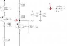
Put your meter negative lead on the regulated output (the -104 volts) and measure the voltage on R171. Measure to the end that goes to the emitter of Q128.
What do you get?
Keeping the negative meter lead where it is now measure on to R168 to the end that goes to Q128 base.
What do you get?
Now measure to the other end of R168.
What do you get?
And the next checks are...
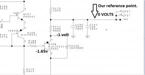
Now put your meter negative lead on the -Pre Reg rail (point 3 on the diagram) which is the unregulated supply because we will use this as a reference point.
What voltage do get on R157 (which is the base Q119 and Q123)
What is the voltage on R156?
What is the voltage on R158?
A problem with Q123 (open circuit) could cause your fault.
A problem with Q119 (leaky) could also do this.
Just remind me 🙂 Did you check R164 and R165 out of circuit?
...so lets work back from the output this time.
Put your meter negative lead on the regulated output (the -104 volts) and measure the voltage on R171. Measure to the end that goes to the emitter of Q128.
What do you get?
Keeping the negative meter lead where it is now measure on to R168 to the end that goes to Q128 base.
What do you get?
Now measure to the other end of R168.
What do you get?
Put your meter negative lead on the regulated output (the -104 volts) and measure the voltage on R171. Measure to the end that goes to the emitter of Q128: 1,06V
Keeping the negative meter lead where it is now measure on to R168 to the end that goes to Q128 base: 1,649V
Now measure to the other end of R168: 0,008 V
And the next checks are...
Now put your meter negative lead on the -Pre Reg rail (point 3 on the diagram) which is the unregulated supply because we will use this as a reference point.
What voltage do get on R157 (which is the base Q119 and Q123)
What is the voltage on R156?
What is the voltage on R158?
Just remind me 🙂 Did you check R164 and R165 out of circuit?
What voltage do get on R157 (which is the base Q119 and Q123): 0,684V
What is the voltage on R156? 0,082V
What is the voltage on R158? 0,09V
Did you check R164 and R165 out of circuit? No, i will do it tomorrow
Negative lead on the output, then measure to the emitter.
Yes, this is it.
Actually you want the voltage on the R171's ends, right?
I would expect about - 1 or 2 volts on the end of R171 that goes to the emitter and the same again + around 0.65 volts on R168.
On R171: it is 1,06V
measured at both ends of R171
I can not reach the emitter of Q128 cause the VG board is on top.
measured at both ends of R171
I can not reach the emitter of Q128 cause the VG board is on top.
Yes, this is it.
Actually you want the voltage on the R171's ends, right?
Your meter negative goes on the output and stays there for now.
On one end of R171 you should see zero volts because it is the same point as the output.
On the other end you should see a low voltage that will depend on the current draw through the 10 ohm. It will be low.
The voltage on R168 (base of transistor) should be the same as R171 plus another 0.65 volts.
Put your meter negative lead on the regulated output (the -104 volts) and measure the voltage on R171. Measure to the end that goes to the emitter of Q128: 1,06V
Keeping the negative meter lead where it is now measure on to R168 to the end that goes to Q128 base: 1,649V
Now measure to the other end of R168: 0,008 V
It looks correct to me - maybe a misunderstanding?
R171 (between ends): 1,06V
-Vreg to Q128 Base: 1,649V
R168 (between ends): 0,008V (in other words between Q128 Base and Q126 Collector.
so the Ve-b of Q128 is exactly 0,589V
(don't forget that i have changed the Q126,Q128 couple days ago)
let's continue tomorrow.... i 'm also tired.... thx anyway
(don't forget that i have changed the Q126,Q128 couple days ago)
let's continue tomorrow.... i 'm also tired.... thx anyway
It looks correct to me - maybe a misunderstanding?
R171 (between ends): 1,06V
-Vreg to Q128 Base: 1,649V
R168 (between ends): 0,008V (in other words between Q128 Base and Q126 Collector.
Those three readings all look good at this point

so the Ve-b of Q128 is exactly 0,589V
(don't forget that i have changed the Q126,Q128 couple days ago)
let's continue tomorrow.... i 'm also tired.... thx anyway
Yes, tomorrow 🙂
(Vbe should be in a range of around 550 to 750 millivolts depending on the transistor and how hard it is being turned on. Polarity depends whether it is NPN or PNP, PNP has the emitter more positive)
Hi Mooly,
Sorry to interfere and with all respect for your attempts to find the error, I have the following remark.
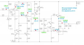
Current source Q124/Q125 should supply 21mA of current to be divided equally by the current mirror Q119/Q123 below the Q121/Q122.
But instead of the 10.5mA x 49R9 = 550mV that should be measured in resp R156 and R158, Thebe only measured 80mV, a clear indication that this current that can't go anywhere else is not the 21mA it should be, but only something like 3mA.
That could also explain why the two bases of Q121 and Q122 have a much lower measured voltage value as expected.
See image below measured in blue by Thebe vs expected in green by LTSpice.
Hans
Sorry to interfere and with all respect for your attempts to find the error, I have the following remark.
Current source Q124/Q125 should supply 21mA of current to be divided equally by the current mirror Q119/Q123 below the Q121/Q122.
But instead of the 10.5mA x 49R9 = 550mV that should be measured in resp R156 and R158, Thebe only measured 80mV, a clear indication that this current that can't go anywhere else is not the 21mA it should be, but only something like 3mA.
That could also explain why the two bases of Q121 and Q122 have a much lower measured voltage value as expected.
See image below measured in blue by Thebe vs expected in green by LTSpice.
Hans
Attachments
- Home
- Amplifiers
- Solid State
- Mark Levinson No 335 - NO Bias in one channel / NEED HELP