But which measurements? The last one with ML amplified?
(I used XLR gnd on LS gnd, XLR + on speaker +, 20cm cable, hoping I would not add too much noise)
And which window function?
(I used XLR gnd on LS gnd, XLR + on speaker +, 20cm cable, hoping I would not add too much noise)
And which window function?
Last edited:
1) You could use LS gnd to pin 2 and LS + to Pin 3 of the XLR input.
This will suppress common mode signals.
So first measure the output from the noisy amp through your silent amp on the scope at 10Khz/div on the FFT.
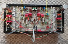
2) Problem with your power supply is that it can only be measured properly with the upper board removed.
Very important are the caps C201 and C202, and maybe without dismantling you could just measure them because they are close to the edge and supply the reference voltage of 36Volt to the power regulator circuits.
3) Did I understand you correctly that the original Spraque cap produces just as much noise as the temp. 470uF ?
4) Did you check the solid electrical connection between heatsinks and chassis to be 0 Ohm ?
Hans
This will suppress common mode signals.
So first measure the output from the noisy amp through your silent amp on the scope at 10Khz/div on the FFT.
2) Problem with your power supply is that it can only be measured properly with the upper board removed.
Very important are the caps C201 and C202, and maybe without dismantling you could just measure them because they are close to the edge and supply the reference voltage of 36Volt to the power regulator circuits.
3) Did I understand you correctly that the original Spraque cap produces just as much noise as the temp. 470uF ?
4) Did you check the solid electrical connection between heatsinks and chassis to be 0 Ohm ?
Hans
I have no idea why things failed in both channels, they are completely independent, unless you have changed components in both channels in the same wrong way.
Could it be C213, where you damaged the mosfet Q216 with a high electrostatic discharge ?
Hans
P.s. What are P17 and P19 doing, I can't find them in my schematic.
Could it be C213, where you damaged the mosfet Q216 with a high electrostatic discharge ?
Hans
P.s. What are P17 and P19 doing, I can't find them in my schematic.
In place of c213 was Nic 10uf50v I replaced it with sprague 517d 10uf100v, really this replacement could not fit?
These are the power supply wires of the channel, they are 190v I confused only in one channel when the Cr207 diode burst. After I called all the parts except for these transistors, all were in good order. But the error was in one channel, and the q216 transistors failed in both channels, this is interesting.
Attachments
Good morning!
Interesting warm-up effect with cold amps: the noise or noise gain doubled (according to ear) after 10 sec. Will try to verify if this is indeed output from noisy ML that's responsible. Could be a components that functions briefly and then breaks down?
1) LS gnd to pin 2 and LS + to Pin 3 xlr
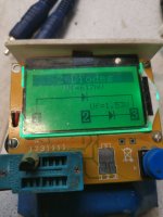
10kHz/div. 0 dB is where the blue M marker is. For 10d/div I had to raise it up to +30dB to see something (last pictures). Used 'Hanning' window.
first, without noisy ML switched on, 20dB/div

now noisy ML on, 20dB/div, had to raise offset slightly

10dB/div, 2 pics with different offset

Hope that helps. If not, I can repeat the measuring.
It seems noise amplitude falls as frequency rises? Does that tell something?
BR
Interesting warm-up effect with cold amps: the noise or noise gain doubled (according to ear) after 10 sec. Will try to verify if this is indeed output from noisy ML that's responsible. Could be a components that functions briefly and then breaks down?
1) LS gnd to pin 2 and LS + to Pin 3 xlr
10kHz/div. 0 dB is where the blue M marker is. For 10d/div I had to raise it up to +30dB to see something (last pictures). Used 'Hanning' window.
first, without noisy ML switched on, 20dB/div
now noisy ML on, 20dB/div, had to raise offset slightly
10dB/div, 2 pics with different offset
Hope that helps. If not, I can repeat the measuring.
It seems noise amplitude falls as frequency rises? Does that tell something?
BR
Last edited:


2) ...Very important are the caps C201 and C202, and maybe without dismantling you could just measure ...
3) Did I understand you correctly that the original Spraque cap produces just as much noise as the temp. 470uF ?
...
2) No chance to get to pins of C201 C202 without boards removed. They are of this Roe type that M.l. replaced I believed.

But I could get to the Rs around C201 C202, e.g. R201 R202 R220 R219 if it's any use to measure V there.
3) Yes, had it back in (with some pin extension for easy of soldering which could be an antenna). But, I will test-replace both Spragues again before I take the boards apart (when my 680uF eventually arrive).
BR
Last edited:
4) Did you check the solid electrical connection between heatsinks and chassis to be 0 Ohm ?
To be sure, I will measure the gnd screw of trans./diodes on heatsink against the alu strip, which should be 10 Ohm, right?
The black anodized makes no connection. So I only measured the screws of the heatsink. Was close to 0 Ohm both sides.
BR


As I'm reading up on FFT and and Rigol 1054z, I realize it's very basic and has very low resolution.
If there was a stable peak in all that noise, we've probably missed it 🙂
BR
If there was a stable peak in all that noise, we've probably missed it 🙂
BR
Last edited:
0 Ohm is what the heatsink to chassis should be, so that's O.K.
Then back to the first image of this morning, noise from the Noisefree amp.
I'm sorry, but have to go in a bit of a technical background:
Your timebase was 0.1msec, so the window size was 0.1*12=1.2mSec.
For the FFT this gives a resolution per filter of 1/1.2msec=833Hz.
Remember I had calculated your Amp to produce 176nV/rtHz, which is 20log(176e-9) = -135dBV/rtHz.
But since your filter width is 833Hz, we have to add 20log(sqrt(833))=29dB.
So your reading should be -135+29= -106dBV.
However your FFT reads ca -90dBV, meaning that almost 100% is scope noise and not from the amp.
So no conclusions can be drawn, other than that your scope is producing -90dBV-29dB=-119dBV/rtHz = 1.1uV/rtHz
which for the assumed 1Mhz BW of your probe means 1.1uV*sqrt(1Mhz)= 1.1mV rms, which seems quite correct.
Conclusion: forget this first measurement.
When adding a second Amp you lift the noise from the first amp by 20*log(22) = 27dB bringing the noise from the calculated -106dBV to -79dBV or 11dB above the -90dBV noise from the scope.
Scope noise will now hardly interfere and readings will become useful.
So If you want a reference noise spectrum, you will have to take one channel of the noisefree amp as input for the other noisefree channel and measure it's output.
I will still comment of the spectra hereafter where you used two amps in series.
Hope I did not overload you with figures, but we are getting somewhere.
Hans
I took the last image in posting #108 and added the division lines that where a bit hard to see.
Three things are apparent:
1) the slope going down from 0Hz to 75Khz by 20dB, this should be as horizontal as the spectrum hereafter.
2) the peak between 10Khz and 25Khz, indicating that some source is jittering in this frequency range, probably your power supply.
3) the fact that the spectrum goes on at the same level after 125kHz, although the BW of your amp is only 122Khz ??
Now could you do the same measurement with the two channels of the noisefree amp, output of one connected to the input of the second channel to get a reference spectrum.
And if possible it would be good to connect a 1K + 1nF in series at the output of the second amp, measuring over the 1nF that is connected to LS- on one side and to the 1K on the other side.
This will function as an anti alias filter and should be visible in your FFT spectrum.
Hans
Attachments

Hans, thanks a lot for the time you are taking.
I will set this up so there is a reference noise FFT, with some anti-aliasing.
I confess I do not fully understand your calculation, but if I get this correctly, the FFT only uses the 1,2ms window the scope currently displays, correct? I thought it is using it's storage memory for averaging, but apparently not, which is why the frequency graph jumps around like crazy.
I found some software that reads data from the Rigol and does a better FFT on PC, it hasn't been updated in a while, but I'll quickly see if I can get it to work.
BR
Yes of course, R201 and R202 are just fine, and you could take the gnd side of R219 / R220.2) No chance to get to pins of C201 C202 without boards removed. They are of this Roe type that M.l. replaced I believed.
But I could get to the Rs around C201 C202, e.g. R201 R202 R220 R219 if it's any use to measure V there.
BR
That will be the next step to measure with your FFT scope through the noisefree 27.5.
The input of the 27.5 as you probably have noticed is AC coupled, so you have no risk of damaging anything when measuring R201 / R202.
Hans
One thing to mention about the connection to the noise free XLR input.
This should be a twisted pair of two wires to reject EMF.
Hans
This should be a twisted pair of two wires to reject EMF.
Hans
Fwiw, I tried out the software and after much fiddling with deprecated python 2.7 stuff I was able to connect the Rigol to my PC.
EDIT: I had to remove these graph because they contain error - more tomorrow.
BR
EDIT: I had to remove these graph because they contain error - more tomorrow.
BR
Last edited:
One thing to mention about the connection to the noise free XLR input.
This should be a twisted pair of two wires to reject EMF.
Hans
Twisted pair wire xlr pin 2+3 is better that shielded (LS Out - = gnd as shield), because it's floating ground, right?
Just asking to be sure.
BR
Last edited:
Twisted pair might be shielded by the chassis gnd on the transmitting side, but on the receiving side only connect pins 2 and 3 to the twisted pair and nothing to pin 1.
But twisting is more important than shielding so don’t bother when you don’t have a twisted cable that isn’t shielded, but keep it short.
Hans
But twisting is more important than shielding so don’t bother when you don’t have a twisted cable that isn’t shielded, but keep it short.
Hans
- Home
- Amplifiers
- Solid State
- Mark Levinson No.27 amplifier,,,NEED HELP