Hi gaetanov, nice job. Everything seems fine, as far as I can see.
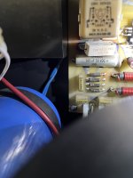
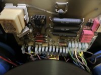
The only curious thing I can notice is, on picture 1828, just under the relay (cubic cream white component at the top left, the resistor's position. This ceramic resistor (3,3Ω, 5W) is OK, but it seems to be soldered not straight (yellow circle): is the left pin soldered?), and the solder joint (red circle), it looks like it is not, or not correctly soldered. If I see well. It would be more informative to have a close picture of this resistor (left pin, is it soldered to the PCB?) and to test if there is continuity between the right leg and the via (copper circle on the PCB). I guess there is a contact, but I doubt this joint is really robust and clean... I can't say right now what's the use and importance of this resistor (I'll try to check this).
Here's what appears to me just before lunch 😉
Sorry I had forgotten to post the image...

Here is a picture of mine below which shows how it should be:

Here is a picture of mine below which shows how it should be:
I would think that this resistor's function is to limit the current surge in the relay when you close the circuit by putting the amp on (yes I know it's odd, when you put a machine on, you close the circuit...).
Hi, the situation is exactly the one that you described, one of the pins is just broken, I mean detached from the board. Moreover the two endpoints look like burned. What do you think I should do? Consider also that I measured the temperature on the two sides of the case and it is quite different: 48C on the left and 55C on the right, this after switching on and keeping the amp silent for one hour.
Attachments
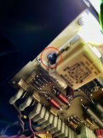
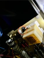
Hi @gaetanov, it is not good. the PCB is burnt on the 2 sides of the resistor which is probably short-circuited, if I'm not wrong. U=RI -> R=U/I. If R is 0 (short-circuit), U (voltage) being constant more or less, I (current) rises suddenly and this can be the cause of the burning. More skilled readers will correct me if I'm mistaking.
Here are 2 pictures (component side and copper side) of how it should be:

The yellow rectangle shows the position of the resistor:

One side of the resistor is connected to the coil of the relay (pin #1), the other side is connected:
Nevertheless, working or not, I'd say you HAVE to fix that issue before doing anything else. That's what I'd do myself. Test the diodes, the capacitor, and of course the resistor. And maybe the relay, since if some current (too much) has been flowing through it, is the coil still OK?
Without being able to test all that myself, I'm a little bit short of ideas... But I'm certain some qualified tech around here is able to help you in what to do first (and what NOT to do...). Sorry to be unable to assist more on that particular issue, but I'm willing to read and understand the expert's advice!
I didn't draw the schema at the time (no need to do so), but maybe I'm going to try this. It's necessary to understand all that.
Good evening 😉
Here are 2 pictures (component side and copper side) of how it should be:
The yellow rectangle shows the position of the resistor:
One side of the resistor is connected to the coil of the relay (pin #1), the other side is connected:
- with the cathodes of 2 diodes which could be the positive output of a diode rectifier bridge (the 4 diodes)
- and with the positive pin of the small brown EKO 10µF/63V capacitor
Nevertheless, working or not, I'd say you HAVE to fix that issue before doing anything else. That's what I'd do myself. Test the diodes, the capacitor, and of course the resistor. And maybe the relay, since if some current (too much) has been flowing through it, is the coil still OK?
Without being able to test all that myself, I'm a little bit short of ideas... But I'm certain some qualified tech around here is able to help you in what to do first (and what NOT to do...). Sorry to be unable to assist more on that particular issue, but I'm willing to read and understand the expert's advice!
I didn't draw the schema at the time (no need to do so), but maybe I'm going to try this. It's necessary to understand all that.
Good evening 😉
Hi @perelman ,
Once again thank you for your patience. I quickly measured the resistor in place and it shows about 47 Ohms, this means it is not shorted, if I'm not wrong. In any case it is true that I must fix it. The annoying thing is that the seller doesn't want to admit that this is a real problem, incredibly.
Once again thank you for your patience. I quickly measured the resistor in place and it shows about 47 Ohms, this means it is not shorted, if I'm not wrong. In any case it is true that I must fix it. The annoying thing is that the seller doesn't want to admit that this is a real problem, incredibly.
Good morning, I was probably mistaken writing that the resistor is good, it's value is quite unstable and needs much better check. Any suggestions about how to disassemble and extract the board?
Just cut the resistor wires, keeping enough length to be able to pull them out with a plyer when heating the solder point.
Then with a sucker or with desoldering braid clean the soldering islands while freeing the via.
Having done that you can easily put a new resistor in place and solder the guy.
Hans
Then with a sucker or with desoldering braid clean the soldering islands while freeing the via.
Having done that you can easily put a new resistor in place and solder the guy.
Hans
This board is easy to get free (4 screws), AFTER you have unplugged all connectors... This would allow to see how much is burnt behind what's visible, clean it if necessary/possible, and solder a new resistor properly.
Of course, if it is not difficult, it takes a little bit of time since you've got to mark all connectors/wires & photos to keep it right when you put it back.
That's how I would do, but it may not be absolutely necessary.
Here's a quick reminder I draw when I did mine (wire colours):

@Hans Polak Do you think the only damaged component is that resistor? And what happened, according to you? And since I know you're an expert, what's the use of this resistor?
Good day all.
Of course, if it is not difficult, it takes a little bit of time since you've got to mark all connectors/wires & photos to keep it right when you put it back.
That's how I would do, but it may not be absolutely necessary.
Here's a quick reminder I draw when I did mine (wire colours):
@Hans Polak Do you think the only damaged component is that resistor? And what happened, according to you? And since I know you're an expert, what's the use of this resistor?
Good day all.
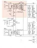
I don't have a schematic of this part, but since there is a natural evolution between ongoing models, I looked at the primary power side of the ML23.
See the schematic below, where in line with the transformers rectifiers were placed to block DC from the mains supply.
Where the ML23 has 2 DC blockers, the ML-9 has only one, and instead of a rectifier block, they use two separate diodes as it seems.
You can see the same three 10R resistors and the two 10.000uF caps between the two amps.
The 3.3R resistor that's discussed here, can IMO be compared with the 2.2R resistor R302 in the schematic below.
Hans
Attachments

This is great, thank you 🙂This board is easy to get free (4 screws), AFTER you have unplugged all connectors... This would allow to see how much is burnt behind what's visible, clean it if necessary/possible, and solder a new resistor properly.
Of course, if it is not difficult, it takes a little bit of time since you've got to mark all connectors/wires & photos to keep it right when you put it back.
That's how I would do, but it may not be absolutely necessary.
Here's a quick reminder I draw when I did mine (wire colours):
View attachment 1221393
@Hans Polak Do you think the only damaged component is that resistor? And what happened, according to you? And since I know you're an expert, what's the use of this resistor?
Good day all.
In order to remove the screws, shouldn't I disassemble the front face of the external case? That one I am not sure how to do...
This is very interesting, thank you @Hans Polak. This means that this network acts as protection on the eventually incoming DCI don't have a schematic of this part, but since there is a natural evolution between ongoing models, I looked at the primary power side of the ML23.
See the schematic below, where in line with the transformers rectifiers were placed to block DC from the mains supply.
Where the ML23 has 2 DC blockers, the ML-9 has only one, and instead of a rectifier block, they use two separate diodes as it seems.
You can see the same three 10R resistors and the two 10.000uF caps between the two amps.
The 3.3R resistor that's discussed here, can IMO be compared with the 2.2R resistor R302 in the schematic below.
Hans
I think (from my memories) that it is simpler to plug the connectors out. Then access is somewhat easy to the 4 screws. That's what I remember...shouldn't I disassemble the front face of the external case?
Hi,
Do you think that such fault could have been caused by plugging the amp into a 220V socket while it was still set on 110?
I know that these amps don't have any external switch and must be properly configured accessing them internally.
Do you think that such fault could have been caused by plugging the amp into a 220V socket while it was still set on 110?
I know that these amps don't have any external switch and must be properly configured accessing them internally.
Maybe the originsl 3.3R was burnt in the past and somewhat clumsy replaced by a 33R resistor.
This is not how ML places resistors.
Hans
This is not how ML places resistors.
Hans
1) I bought my ML-9 from eBay US, it was 110V rated and I had it professionally modified to 230V by an ex-tech from the first ML importer in France in the late 70s, so the guy knows all about it. I can't say what he did exactly, at the time I was not aware of anything about all that. He just asserted that the amp was in good shape, capacitors OK in particular. It was in 2009.
2) Since the resistor on mine is rated at 3.3Ω, I guess it should be replaced by same value on yours. Something like this. @Hans Polak is right.
2) Since the resistor on mine is rated at 3.3Ω, I guess it should be replaced by same value on yours. Something like this. @Hans Polak is right.
Last edited:
Yes indeed. Very strange. At least, except if someone says the opposite, I'd take this board out and more or less check some components. Then you'll see how this PCB looks on the soldering side (beside the burnt part around the resistor). And since it has probably been "touched" before, I'd say it's a good practice to see what all that is looking like. And also, you'll get a much easier access to what you have to do.
My 2c.
My 2c.
You know, I was enthusiast and, although it was not a cheap purchase, I was ready to accept to fix something, but this evident and heavy modification suggests me to ask for a refund and send it back to the seller. I am a bit sad, honestly.
I want to thank you @perelman for the fantastic support you provided and @Hans Polak for your precious suggestions.
If I will find another ML9 on sale I will be happy to buy it, it looks really gorgeous and it si built in a fantastic way, unless somebody puts his hands inside to make a mess like this.
Take care
Gaetano
- Home
- Amplifiers
- Solid State
- Mark Levinson ML-9 recapping (1985)