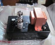
Hi.I am clonning Marantz MA9s2 non compramise amplifier.I am about to finish but i could not find much information about choke (L002 please check pictures attached.)
Is it ferrite core or air coil? We only know the inductance (2x180mH ) but do not know the wire gauge and toroidal core.Any ideas? Thanks in advance.Best regards


Is it ferrite core or air coil? We only know the inductance (2x180mH ) but do not know the wire gauge and toroidal core.Any ideas? Thanks in advance.Best regards
looked to me that is a common mode mode choke for filtering out RFI from the dc psu...
a ferrite most likely, you can find them sold on line....pc crt monitors and crt color tv's have those but i doubt the ampacity is big enough for an audio ampflifier...
https://docs.rs-online.com/f8dd/0900766b816de17a.pdf
a ferrite most likely, you can find them sold on line....pc crt monitors and crt color tv's have those but i doubt the ampacity is big enough for an audio ampflifier...
https://docs.rs-online.com/f8dd/0900766b816de17a.pdf
Hi.It seems there is about 24v loss on toroid.Is it inductive resistance or resistive loss? It seems it is before dc filtering before the capacitors.How can we calculate it?
According to my calculations there is about 50mA flowing through the choke filter.
According to my calculations there is about 50mA flowing through the choke filter.
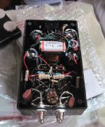
Hi. I am asking the big toroidal filter specs behind the white filter.Not the white one. It is big black one.
The "big black one", as you call it is a mains toroidal power transformer - the L001 on the schematics.
No it is not. Mains toroidal transformer is on the left of amp. Toroidal choke is under the Hdam sa modules. Please check datasheet. There is also L003 L004 and L005 ferrite cores
Hmmm... you ain't gonna like my calculation... but... I did an x-check using two different approaches... and I arrived at... a 12A DC common mode choke, 180mili H. Big motha... it comes to an individual interpretation of what the DC rating of this choke should be... I used a pretty severe case, but everything was as per the specifications. This would be enormous if done with a typical E-Core laminate. They may have used a special toroidal core material as well - a highly inductive one.
But, that amp in general... OMG... the design, grounding, connection of zero PS point to chassis, PCB layouts, creation (design) AND execution of 0V reference potential for main PCB... superb in every way. Unbelievable. Also, only 4 gain stages, highly optimised input & VAS ... and only 3 resistors in a signal chain.... a true differential approach.... get outa here.
I'd ditch the HDAMs... e.g. the pre-amp section, altogether.
A man can learn so much from that design.
Last edited:
best way is to get to look at the actual unit, if i were doing it, based on the schematics, i will know what to do..
According to my calculations Choke has about 250ohm dc resistance and 113ohm inductive resistance.
Are your calculations based on quiescent current draw + whatever the current draw is from other PCBs?
post #14, this is a low power supply for the front ends, and so i have no problems with his calculations. seems typical..

i suspect that the front end of the amp this psu supplied is class A so that loading is pretty much constant...Are your calculations based on quiescent current draw + whatever the current draw is from other PCBs?
Fellas,
Have a better look... the choke supplies current to the main amplifier section. This is why my calculations pointed to a 12A rating... the worst-case power consumption/output, 4-ohm load.
The inductance could be calculated only if the amp is examined under load on a test bench.
I think I've provided enough info here, for something that should not really be encouraged... ripoff of the original design.
yes, that part where there is a common mode choke supplied -+65vdc to the amplifier front end, the input transimpedance and the VAS...notice that that psu just used 4700/80v, such small filters are just okay there....
there is another psu that supplied rails to the output stage, these one used 33000ufd/63volt caps ad probably +-50vdc rails, this is the higher current psu for the output supply......such designs are typical practice of Japanese, the reason being, that the output stage clips first, and the front end never clipped....such design principle was also advocated in the 70's by William Marshal Leach of Georgia Tech....
there is another psu that supplied rails to the output stage, these one used 33000ufd/63volt caps ad probably +-50vdc rails, this is the higher current psu for the output supply......such designs are typical practice of Japanese, the reason being, that the output stage clips first, and the front end never clipped....such design principle was also advocated in the 70's by William Marshal Leach of Georgia Tech....
- Home
- Amplifiers
- Power Supplies
- Marantz MA9S2 choke input power supply