SimontY said:Behold, the alien craft has landed!!! Can it breathe our air?? 😕
Yes it can but only for 3 hours. I need to fit a fluffle valve to it and supply it with methane (mainly from my own blow hole)
😀

Wow, cool job Brent!
Will order myself some thin coax this week 😀
What kind did you use, and did you terminate it?
Ray.
Will order myself some thin coax this week 😀
What kind did you use, and did you terminate it?
Ray.
6h5c said:Wow, cool job Brent!
Will order myself some thin coax this week 😀
What kind did you use, and did you terminate it?
Ray.
Here is the manufacturer
http://www.hubersuhner.com/hs-rf-cables
Its 50 ohm +/- 2 ohm.
We have it here at work, it's for connecting £20000+ calibrators together that read ohms and current down to 8.5 decimal places.
So I thought it would be ok.
They are soldered direct, If I need to take the pcb out I will just undo the two screws on the mech that hold the pcb in place.
Ray do you live anywhere near Eindhoven.
If so FLUKE will have thousands of these. They scrap perfectly good cables like this all the time.
Well thats what they do in the UK.
If so FLUKE will have thousands of these. They scrap perfectly good cables like this all the time.
Well thats what they do in the UK.
rowemeister said:We have it here at work, it's for connecting £20000+ calibrators together that read ohms and current down to 8.5 decimal places.
So I thought it would be ok.
I suppose what's good enough for £20000+ calibrators is good enough for a CD63KI 😀
They are soldered direct, If I need to take the pcb out I will just undo the two screws on the mech that hold the pcb in place.
So you didn't use any series/termination 50R resistors?
Ray do you live anywhere near Eindhoven.
If so FLUKE will have thousands of these. They scrap perfectly good cables like this all the time. Well thats what they do in the UK.
No, not very near. But I have a dump-store at 1/2 hr. drive from my place. It's worth to take a look and see what they've got. Maybe some nice MIL-spec coax 😀
Ray.
No Ray not on the SIDA and SICK lines.
I kept the 10PF cap and 390 ohm resistor on the DAC clock out for Decoder.
Is it really that necessary on such small runs? I'm not sure.
I kept the 10PF cap and 390 ohm resistor on the DAC clock out for Decoder.
Is it really that necessary on such small runs? I'm not sure.
I'm not sure either
I don't have a good scope to take a look at the waveform. But technically there could be reflections bouncing back and forward that interfere with the original waveform.
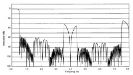
I've done some more tinkering with the passive filters, and did some more simulations. Here's a PDF with the latest i've come up with.
The circuit of the Butterworth filters matches that of the player's PCB, so it's easier to fit the components on the original board. Also the input impedance is much more constant compared to Thorsten's circuit. But I don't know at what impedance the DAC is most happy.
I made filters with various attenuation, because I still have to decide what buffer i'm going to use. Maybe the modified HDAM, or a Lundahl tranny, or a tubestage. Have to do some more experiments.
Regards,
Ray.
I don't have a good scope to take a look at the waveform. But technically there could be reflections bouncing back and forward that interfere with the original waveform.
I've done some more tinkering with the passive filters, and did some more simulations. Here's a PDF with the latest i've come up with.
The circuit of the Butterworth filters matches that of the player's PCB, so it's easier to fit the components on the original board. Also the input impedance is much more constant compared to Thorsten's circuit. But I don't know at what impedance the DAC is most happy.
I made filters with various attenuation, because I still have to decide what buffer i'm going to use. Maybe the modified HDAM, or a Lundahl tranny, or a tubestage. Have to do some more experiments.
Regards,
Ray.
Attachments
6h5c said:I'm not sure either
I don't have a good scope to take a look at the waveform. But technically there could be reflections bouncing back and forward that interfere with the original waveform.
I've done some more tinkering with the passive filters, and did some more simulations. Here's a PDF with the latest i've come up with.
The circuit of the Butterworth filters matches that of the player's PCB, so it's easier to fit the components on the original board. Also the input impedance is much more constant compared to Thorsten's circuit. But I don't know at what impedance the DAC is most happy.
I made filters with various attenuation, because I still have to decide what buffer i'm going to use. Maybe the modified HDAM, or a Lundahl tranny, or a tubestage. Have to do some more experiments.
Regards,
Ray.
All I can report is that the sound is much better now.
I wasnt going to add anything extra in until I know better

6h5c said:I'm not sure either
I don't have a good scope to take a look at the waveform. But technically there could be reflections bouncing back and forward that interfere with the original waveform.
I've done some more tinkering with the passive filters, and did some more simulations. Here's a PDF with the latest i've come up with.
The circuit of the Butterworth filters matches that of the player's PCB, so it's easier to fit the components on the original board. Also the input impedance is much more constant compared to Thorsten's circuit. But I don't know at what impedance the DAC is most happy.
I made filters with various attenuation, because I still have to decide what buffer i'm going to use. Maybe the modified HDAM, or a Lundahl tranny, or a tubestage. Have to do some more experiments.
Regards,
Ray.
Ray - could you explain the figures please.
Attenuation dB, ? , attenuation at 20kHz
My turn to ask the silly question !
Andy
rowemeister said:All I can report is that the sound is much better now.
I wasnt going to add anything extra in until I know better
Yeah, better to do one step at a time. I'm going to try the coax anyway.
poynton said:Ray - could you explain the figures please.
Attenuation dB, ? , attenuation at 20kHz
My turn to ask the silly question !
Andy
No, no, not silly. Are you familiar with dB's? You can calculate it by taking the log of the amplification factor of a circuit and multiply that by 20, eg. 20*log (Uout/Uin). If you do that for every circuit, you can calculate total amplification just by adding and subtracting dB's instead of having to multiply and divide all the amplification factors.
The original Marantz circuit amplifies the DAC signal with 8.6dB. That's a factor 2.7, and that's because 27k divided by 10k = 2.7 (no coincidence...).
If you want to maintain the original output level, you have to build a circuit that behaves the same.
Because the filter is passive, it has a loss in the passband. That's unavoidable. The first dB figure is this loss.
If the filter has a 6dB loss, that means the following buffer circuit must amplify about 14/15dB to make up for this loss, to reach a 8.6dB output level.
The second figure is the -3dB corner frequency, and the third figure is the loss at 20kHz.
Regards,
Ray.
6h5c said:I'm not sure either
I don't have a good scope to take a look at the waveform. But technically there could be reflections bouncing back and forward that interfere with the original waveform.
I've done some more tinkering with the passive filters, and did some more simulations. Here's a PDF with the latest i've come up with.
The circuit of the Butterworth filters matches that of the player's PCB, so it's easier to fit the components on the original board. Also the input impedance is much more constant compared to Thorsten's circuit. But I don't know at what impedance the DAC is most happy.
I made filters with various attenuation, because I still have to decide what buffer i'm going to use. Maybe the modified HDAM, or a Lundahl tranny, or a tubestage. Have to do some more experiments.
Regards,
Ray.
have you done any measurements as to the 44.1kHz output from the dac.
would be interesting to see how much of this frequency is corrupting the output.
if 3db is an audible difference how many db reduction then needed to to clean out the higher rubbish (harmonics).
this could also effect the lower octives 22.05kHz 11.025kHz
may be best to see output into spectrum analizer?
allan
The listening test.
I am a happy person 😀
As reported earlier the listening tests at home revealed the same improvements.
Treble is much more precise and articulate.
Top of the mid range is clearer/open - more air.
Bottom of mid is slightly better.
Bass has even more resonance on piano and there is a definate increase in the bass I can feel through the floor to my sitting position (we all have sitting positions don't we 🙂 )
Obviously I recommend the reg's mods as seperating all rails improves the dynamics of the sound.
I also recommend the coax mod, you will be really happy with the treble and top end of the vocals with this.
I don't know how much the coax mod will improve a standard player but who on this post has one 😀
Now what do I do now...... think i'll re wire my amp signal line with silver wire.
That's not really the problem, the noise is wider-spectrum and higher up the frequency range, because the PWM output is unfiltered. Remember, square wave = lots of harmonics.have you done any measurements as to the 44.1kHz output from the dac.
Apart from that, there is a lurch upward in the DAC's noise floor about 340Khz (8Fs) if I remember correctly.
acw said:
this could also effect the lower octives 22.05kHz 11.025kHz
may be best to see output into spectrum analizer?
allan
OOOps low pass filter🙄
"analizer" he he analyzer but who noticed
never post at the end of work day😀
allan
acw said:have you done any measurements as to the 44.1kHz output from the dac.
would be interesting to see how much of this frequency is corrupting the output.
if 3db is an audible difference how many db reduction then needed to to clean out the higher rubbish (harmonics).
this could also effect the lower octives 22.05kHz 11.025kHz
may be best to see output into spectrum analizer?
allan
Hi Allan,
No, i'm afraid I don't have a spectrum analyzer 🙁
The datasheet states a 53dB attenuation at Fs, the sample frequency is already suppressed in the DAC. The passive filters attenuate about 7...8dB at this frequency, so overall there would be at least -60dB at 44.1kHz.
martin clark said:That's not really the problem, the noise is wider-spectrum and higher up the frequency range, because the PWM output is unfiltered. Remember, square wave = lots of harmonics.
That too!
Would that be the source of the 22mV noise I measure with my poor 20MHz scope at the output?
Regards,
Ray.
Attachments
Hi Rowemeister,
Since I last looked, you've been busy!
Did you ever establish if the blue LEDs made any difference?
In a previous job I recall using some very small (yet probably pricey) coax connectors. Maybe they could be used for the coax traversing the two boards?
Cheers,
Phil
Since I last looked, you've been busy!
Did you ever establish if the blue LEDs made any difference?
In a previous job I recall using some very small (yet probably pricey) coax connectors. Maybe they could be used for the coax traversing the two boards?
Cheers,
Phil
Found them on Farnell
http://uk.farnell.com/jsp/endecaSea...ectors&N=401+1003916&Ntt=&Ntk=&comSearch=true
Not sure how usable they'd be, they're not the cheapest connectors, but well made.
Cheers,
Phil
http://uk.farnell.com/jsp/endecaSea...ectors&N=401+1003916&Ntt=&Ntk=&comSearch=true
Not sure how usable they'd be, they're not the cheapest connectors, but well made.
Cheers,
Phil
philpoole said:Hi Rowemeister,
Since I last looked, you've been busy!
Did you ever establish if the blue LEDs made any difference?
In a previous job I recall using some very small (yet probably pricey) coax connectors. Maybe they could be used for the coax traversing the two boards?
Cheers,
Phil
Yeah very busy. lol
The blue LED mod. Well I have @ work done a few blind tests on one track with my work mate switching the led on and off (I dont know which position it is in).
One way I could hear a very slight improvement in the very delicate treble (symbols etc) and a miniscule improvement in low bass.
I did this test 6 times each lasting 15mins ish.
I then told my mate to stop in the position where I believed it had very slight improvements.
Guess what... LEDs on. mmmm
I need to test at home too, but the wife is not happy about flicking a switch all night lol
ray
i did read somewhere about the limitation of cd and the 44.1kHz
the reason sacd, 100kHz and 192khz sample?
the 22mV noise?
you have problem with 20mHz scope
mine is a 5mHz velleman portable
i have been looking for better scope, found this
http://www.bitscope.com/ , shouldhave got one a couple of years ago.
with analizer(wnglish--web english)
rowemeister
- Home
- Source & Line
- Digital Source
- Marantz CD63 & CD67 mods list