Brakspear sorry you must have been replying at the same time so I didn't see it.
I basically have what you describe apart from the series R from pin 7 to RCA....but having gone straight to new plugs I've omitted the R661/662 path and anything around there I guess
Shall see what tomorrow brings!
I basically have what you describe apart from the series R from pin 7 to RCA....but having gone straight to new plugs I've omitted the R661/662 path and anything around there I guess
Shall see what tomorrow brings!
Hello,
I have bought a used CD6002 player from Marantz.
I would like to improve its sound.
Any suggested mod for this player that doesn't have OPA ?
Thanks
I have bought a used CD6002 player from Marantz.
I would like to improve its sound.
Any suggested mod for this player that doesn't have OPA ?
Thanks
Any suggested mod for this player that doesn't have OPA ?
Things you could try:
a) taking the output before the output caps via e.g. 47R resistor (if the DC offset is within reasonable limits);
Separate the output stage power rails for channels.
b) use DOS output stage;
c) use the filter part of the DOS output stage and feed the signal out via e.g. OPA132/134 or other type of opamp.
d) move the project to the CD6002 thread 😉 .
Guys,
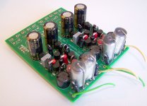
if someone needs a used DOS with CFP hack then it's yours for shipping cost.
PM.
I am interested... 🙂
Hello
I made small modification in my CD-63. I only repleaced caps in power unit and op-amps. After that when I play cd I hear only noise.
Can someone support me?
I made small modification in my CD-63. I only repleaced caps in power unit and op-amps. After that when I play cd I hear only noise.
Can someone support me?
As starting point you could check the voltages at regulator outputs and consumer chips power inputs.
Probably you have broken something in the process or have something trivial as loose cable connection...
Probably you have broken something in the process or have something trivial as loose cable connection...
If the voltages check out OK, the ribbon cable from the transport to the main board is a frequent source of bad connections - check to see if the pins in the socket have been bent flat and carefully bend them back using a needle if necessary. Just disconnecting this cable can wobble the socket enough to break the solder joints at a pin or two, so check the underside of the socket as well.
If none of this helps, please list the part numbers of the caps you replaced and any voltages measured, it will help us to help you.🙂
If none of this helps, please list the part numbers of the caps you replaced and any voltages measured, it will help us to help you.🙂
Hello
I measured voltage in power unit. Results are:
20,8 V on D801, D802 result 21,4 V
-20,8 V on D803, D804 result -21,4 V
11,5 V on D811, D812 result 11,7 V
-12,1 V on D813, D814 result -12,0 V
After voltage regulators
+5 V on U163 result +5 V
+12 V on U218 result +12,1 V
-12 V on U216 result -11,7 V
+10 V on U161 result +11,4 V
-10 V on U162 result -12,2 V
I checked 0,0V on op-amps
RCH 1)-22,3mV 2)1,4V 3)1,4V 7)23,9mV
LCH 1)-15,3mV 2)1,4V 3)1,4V 7)21,8mV
On op-amps I repleaced 4pcs caps Silmic II 220uF/25V
Have you fitted suitable opamps?
What was originally in there and what did you replace them with? Could they be fakes?
What was originally in there and what did you replace them with? Could they be fakes?
Another likely problem could be that you have dropped a blob of solder onto the print side of the PCB shorting two points out, possibly around some of the processing chips. Its obviously something that has happened while you have been working on this. Visually go over the PCB very carefully and recheck all your work.
Mooly, madis64
Thanks a lot for your support my thinking. You are right, there is not mod failure.
I see my job mistake. To disable headphone circuit instead to remove jumpers U271/272 I have removed U171/172. Stupid mistake🙂
Thanks a lot for your support my thinking. You are right, there is not mod failure.
I see my job mistake. To disable headphone circuit instead to remove jumpers U271/272 I have removed U171/172. Stupid mistake🙂
Incredible how this thread continues to survive. Certainly a tribute to an excellent player.
Recently I helped a friend of mine replace the mechanism in his Marantz CD67SE. So I bought this for him.
For Philips Laufwerk VAM 1202 VAM 1201 CDM 12.1 CDM 12.2 Original- ** Neuware ** | eBay
An experienced technician installed it, so that part was done OK.
As a result hiz player is now reading CDs that it didn't before, but CDs spin off center and vibrate.
The culprits seem to be the original clamps, that apparently do not work well with this mechanism. What solutions can be applied?
Are there clamp rings anywhere that fit better this new transport? Where can I find those parts?
I already contacted the seller, but I do not expect him to solve it. eBay is not what it was anymore. They now do not care of after sale customers.
Clamp from VAM is not the same as the CDM one. Just remove the sub-frame on rubber and move it to the original CDM frame and voilä !
Clamp from VAM is not the same as the CDM one. Just remove the sub-frame on rubber and move it to the original CDM frame and voilä !
Can you please explain this a little more?
I would have to explain this to the technician that installed the mechanism.
- Home
- Source & Line
- Digital Source
- Marantz CD63 & CD67 mods list