Yes it has an OPEN/CLOSE button. It's called RC-63CD and can be found on e-bay for around 10 bucks.
My suggestion only works if the tray always opens fully first, and then closes by itself by the way. If you're having trouble finding a replacement tactile-switch, you can also swap one with a button you seldom use.
My suggestion only works if the tray always opens fully first, and then closes by itself by the way. If you're having trouble finding a replacement tactile-switch, you can also swap one with a button you seldom use.
If you have a Universal remote control, maybe you can program it use with the player.
I lost mine too. I own a Marantz amplifier and the amp remote control works also on the CD63 KI .........well everything except volume control for the headphones output.
I lost mine too. I own a Marantz amplifier and the amp remote control works also on the CD63 KI .........well everything except volume control for the headphones output.
If you have a Universal remote control, maybe you can program it use with the player.
I lost mine too. I own a Marantz amplifier and the amp remote control works also on the CD63 KI .........well everything except volume control for the headphones output.
The guy I bought it did supply a remote but it's a Phillips. It does everything except Open/Close.🙁
I'm not sure it is switch bounce. If I stop a cd and hit Open immediately it opens ok!
Do any of the esteemed viewers/contributors know if the tx on the CD63 and CD67 are the same?
I have quickly gone through the circuit diagrams of CD63 and CD67 and it seems to me that the 2 TXs are the same.Do any of the esteemed viewers/contributors know if the tx on the CD63 and CD67 are the same?
Just check it up and confirm yourself as I have no modding experience with CD67.
Thanks higlander. Another very very, in fact the most stupid question I bet has ever been asked on here.
I have a CD63 and CD67, and took the transports out of both, and have now mixed them up (groan).
Anyway, one has a lot of resistors and other components on it, the other hasn't, just a chip.
Which one is which?
I have a CD63 and CD67, and took the transports out of both, and have now mixed them up (groan).
Anyway, one has a lot of resistors and other components on it, the other hasn't, just a chip.
Which one is which?
8th CD63 modding project
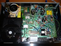
I have spent two days modding my 8th CD63 for a friend of mine. This time due to his budget constraints I did not use very top grade components. Nevertheless the result is still very good. I have uploaded a photo for experience sharing. Everything is complete except the relay for the muting circuit which I am waiting for its delivery. Total cost of electronic parts for the project inclusive of the basic CD63 is less than £150 😛 Not too bad at all.
I have spent two days modding my 8th CD63 for a friend of mine. This time due to his budget constraints I did not use very top grade components. Nevertheless the result is still very good. I have uploaded a photo for experience sharing. Everything is complete except the relay for the muting circuit which I am waiting for its delivery. Total cost of electronic parts for the project inclusive of the basic CD63 is less than £150 😛 Not too bad at all.
Attachments
CFP DOS with output current sink
This is a quote of Ray's post of over 1 year ago. I never read someone tried his proposal, so I did: I put a transistor current sink in the output, using a 2SC2240 with a resistor of 110R for 10mA current.
I used to have a resistor at the source terminal of T6 (the outputbuffer FET), as most of us seemed to like best. Lately by experimenting, I realised that resistor has a big impact on the sound character (metalfilm or carbonfilm, brand), too much influence to my taste.
So today I put in the current sink and I'm very pleased with the result: far better than could be done with resistors and more neutral and precise sound. I even applied the quick-and-dirty method of getting the base voltage of the other current sink T5 (also a 2SC2240) in the design, so both current sinks have the same base-voltage.
I'd really recommend to try this with your DOS'es, if you're still using a resistor at the source of T6. Maybe your output stages improve just as much as mine did!
With thanks to Ray, regards
Anton
My CFP-DOS statistics: resistors: TAKMAN REX, p.filter capacitors: Styrene, T1,2,6: 2SK170BL, T3,4: 2SA970, T5,7: 2SC2240, 100u Elna SilmicII on supply lines, 2 Belesson superregs 15V, 4.7u Mundorf Supreme dc-blocking cap
Hi, i'm back 🙂
Good to see there's plenty DOS-talk around 😀
Seems the current sink needs some experimenting? Theoretically, it should be an improvement over a resistor. Maybe i'll implement a transistor-LED version in the next batch of boards, just like the one in the input stage. This would be even more versatile, and more easy to tweak to the correct current.
I'm glad you sorted out the sound now, Brent and others. Is it possible you guys could test the board with such a current sink? It's fairly simple to do: replace the FET T7 by a BC550C, replace the 100R resistor (R13) by a LED and insert a 10k resistor from the LED's anode to the +12V. R14 sets the current, it should be around 100R for 10mA to flow through the output buffer.
If you want to do it really quick-and-dirty you could even use the LED's voltage from the input stage and tie T7 base to T5 base 😀.
Ray
This is a quote of Ray's post of over 1 year ago. I never read someone tried his proposal, so I did: I put a transistor current sink in the output, using a 2SC2240 with a resistor of 110R for 10mA current.
I used to have a resistor at the source terminal of T6 (the outputbuffer FET), as most of us seemed to like best. Lately by experimenting, I realised that resistor has a big impact on the sound character (metalfilm or carbonfilm, brand), too much influence to my taste.
So today I put in the current sink and I'm very pleased with the result: far better than could be done with resistors and more neutral and precise sound. I even applied the quick-and-dirty method of getting the base voltage of the other current sink T5 (also a 2SC2240) in the design, so both current sinks have the same base-voltage.
I'd really recommend to try this with your DOS'es, if you're still using a resistor at the source of T6. Maybe your output stages improve just as much as mine did!
With thanks to Ray, regards
Anton
My CFP-DOS statistics: resistors: TAKMAN REX, p.filter capacitors: Styrene, T1,2,6: 2SK170BL, T3,4: 2SA970, T5,7: 2SC2240, 100u Elna SilmicII on supply lines, 2 Belesson superregs 15V, 4.7u Mundorf Supreme dc-blocking cap
Last edited:
Hi Anton,
Good to hear it's not just me that likes a current-sink better 🙂
The new DOS board has room for a FET as a current-sink. Not the fancy transistor-LED solution, but it can easily be tweaked to work that way. The single-FET CCS also sounds way better than the resistor IMHO.
I can recommend the new Mundorf EVO Silver/Gold-Oil caps if you'd like to squeeze some more performance out of the board.
Ray
Last edited:
8th CD63 modding project complete
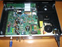
The muting relay arrived yesterday morning and I have just installed it onto the CD63 (the relay is at the bottom left hand corner of the attached photo). Now my 8th CD63 modding project is complete and my friend will pick this up in the weekend 😉
The muting relay arrived yesterday morning and I have just installed it onto the CD63 (the relay is at the bottom left hand corner of the attached photo). Now my 8th CD63 modding project is complete and my friend will pick this up in the weekend 😉
Attachments
Thanks for sharing Highlander.
I have a few questions for you :
- What do you use to shield the ICs ? I've searched farnell, but didnot find anything that seems ok.
- What type of coax cable do you use ? There's so many ref on farnell, I'm lost, I have no idea what to choose.
- Which ref are the RCA socket you put ? I've found many different ones at various prices, and I wonder how much is worth to be spent on this. With the idea in mind, that I would also add the same pair on my amp.
- Last one, what kind of cable (again, ref if possible 😛 ) do you use between RCA socket and the pcb ?
Thanks for sharing Highlander.
I have a few questions for you :
- What do you use to shield the ICs ? I've searched farnell, but didnot find anything that seems ok.
- What type of coax cable do you use ? There's so many ref on farnell, I'm lost, I have no idea what to choose.
- Which ref are the RCA socket you put ? I've found many different ones at various prices, and I wonder how much is worth to be spent on this. With the idea in mind, that I would also add the same pair on my amp.
- Last one, what kind of cable (again, ref if possible 😛 ) do you use between RCA socket and the pcb ?
- The shields are copper foil like this:
http://www.ebay.co.uk/itm/EMI-COPPE...?pt=UK_Sound_Vision_Other&hash=item43bbb4fef6
- I use small sized HF coaxial cable for wifi like this:
http://www.ebay.co.uk/itm/RG316-Coa...osters_Extenders_Antennas&hash=item45fcaa5a87
- RCA sockets are CMC gold plate sockets like this:
CMC Nickel Free Gold Plate RCA Socket 2 pairs/4 pcs | eBay
-for internal connections I use pure OCC copper wires like this:
Pure Stranded UP - OCC Cyro Treated 7N Copper Wire (per ft) | eBay
Last edited:
Good work yet again Highlander!
I was going to use this coax for the clock signals
http://pages.ebay.com/link/?nav=item.view&id=151042367995
But Ray told me that UTP twisted pair cables were just as good, and I have a load of spare cat5 network cabling, so I might just use that instead
I was going to use this coax for the clock signals
http://pages.ebay.com/link/?nav=item.view&id=151042367995
But Ray told me that UTP twisted pair cables were just as good, and I have a load of spare cat5 network cabling, so I might just use that instead
Highlander, I noticed that you have a terminator onto the digital coax out on that player and I've read of people quoting improvements in sound from having a 75ohm terminator on the digital out if it's unused.
If I don't intend to ever use the digital outs on this player any more, I guess that it would be best to remove the connections to the digital outputs as close to the decoder as possible to remove all that unwanted track acting as an aerial?
From what I can tell, the digital output is fed from Pin 2 of the decoder (DOBM) via R514.
Do you guys reckon it'd be worthwhile removing this if I'm not using it and if so, should I just remove R514 to do so or would it be best to somehow terminate it with a resistor to ground close to the decoder?
cheers,
James
Thanks for you answer Higlander.
James, about the Digital Output, I've followed Ray's advise on my CD57 :
Disable Digital Out:
- Remove R114, U172, U196 and U204 to disable the DO signal to the outputs on the back-panel.
- Remove U201 to disable +5V to the optical output connector.
I bet he has done something similar in his CD63 but nothing appears in his modlist for that player.
I don't recommend removing the digital output as you may use this sometime in the future. What I have done is to cut and isolate the the copper strip on the back of the PCB and then hard wire a coaxial cable from as close from the chip to the RCA digital output. This will ensure the best digital signal flow without picking up unwanted interference.Highlander, I noticed that you have a terminator onto the digital coax out on that player and I've read of people quoting improvements in sound from having a 75ohm terminator on the digital out if it's unused.
If I don't intend to ever use the digital outs on this player any more, I guess that it would be best to remove the connections to the digital outputs as close to the decoder as possible to remove all that unwanted track acting as an aerial?
From what I can tell, the digital output is fed from Pin 2 of the decoder (DOBM) via R514.
Do you guys reckon it'd be worthwhile removing this if I'm not using it and if so, should I just remove R514 to do so or would it be best to somehow terminate it with a resistor to ground close to the decoder?
cheers,
James
I am not sure how best the RCA terminator can perform but there is no harm to use one and at least it will prevent dusting the socket 😉
- Home
- Source & Line
- Digital Source
- Marantz CD63 & CD67 mods list