Well now I'm back home I can see that my player takes 1 second to wake up. So from the time constant and the threshold of that device that works out right.
Thomo - didn't you say earlier that it went bananas and won't read the disc anyway? That may be something more serious!
Try off and on quickly....
Thomo - didn't you say earlier that it went bananas and won't read the disc anyway? That may be something more serious!
Try off and on quickly....
Quick Q for Martin:
I'm revamping my DAC chip regs in my 67SE. Only the humble LM317 but anyway...
For the analogue L & R pins (which I've separated by cutting a track) I'm building a double LM317 on veroboard to mount in the gap between where the op-amps used to be. (I now have a separate analogue stage with its own transformer etc.)
I plan to use the now unused analogue winding of the transformer for all four DAC supplies. I already have LM317 for DAC digital and clock gate.
For my double 317 board, my plan is to have output wire and adjust pin ground wire from each 317 out to DAC pins (only an inch or so away) and the ground for input and output caps soldered to the ground plane. Input voltage from where input leg of 7812 was.
Is this a good idea or better to have my decoupling ground and input wired straight to the filter cap. (i.e., wires from where input and gnd of 7812 were to my reg board, then output and sense gnd to DAC pins).
I hope you see what I'm getting at here. Presumably I should avoid connection to the signal ground tracks running from the DAC to the output jacks (where the signal filter caps are grounded as I take my music after the RCRC).
If any of that made sense..... 😀
Is this a good idea or better to have my decoupling ground and input wired straight to the filter cap. (i.e., wires from where >input and gnd of 7812 were to my reg board, then output and sense gnd to DAC pins)
That sounds good to me. AFAIK, the 'upper ' resistor need s to be connected close to the LM317 body between output and the adjust pin, but the 0v sense wir does want returning as close to the 0v of the device to be powered as can be reasonably achieved. The adjust pin decoupling cap only needs to be across the lower, voltage-set resistor though (no need for a second wire to device 0v) because it's the resistor that it 'bypasses'.
Similarly, the output decoupling cap wants to be across the load, even if this is remote from the 317. Any input-decoupling is a lot less sensitive though - so I'd fit it wherever is easiest.
Thanks Martin. so no ground plane for decoupling returns.
I was actually thinking the reg output cap (returned to ground plane or a wire to filter cap as discussed) in addition to the one across the DAC pins which is already there.
I was thinking that as long as my 'sense' ground was wired to the DAC gnd pin, the decoupling returns at the regulator (not the cap across the load) could use the lower impedance ground plane - but you say better to use a wire straight to where 7812 was. If I understand correctly.
One more thing, if the output caps are not ultra-low ESR types (they are Nichicon Muse KZ 100uF/25v) they can sit as close to the output of the LM317 as I like, right?
One more thing, if the output caps are not ultra-low ESR types (they are Nichicon Muse KZ 100uF/25v) they can sit as close to the output of the LM317 as I like, right?
Glen I think garden variety is better here (according to TNT article) KZ is still low ERS I believe. I think its also ok to use low esr as decoupling caps, and from experience thye influence the sound the most.
I couldn't find any data on the ESR of Muse KZ.
I thought they were more like the Elna audio caps in this respect, which I don't believe are low ESR. (Silmic, Cerafine, Starget, etc.)
I thought they were more like the Elna audio caps in this respect, which I don't believe are low ESR. (Silmic, Cerafine, Starget, etc.)
Glenn2 said:I couldn't find any data on the ESR of Muse KZ.
I thought they were more like the Elna audio caps in this respect, which I don't believe are low ESR. (Silmic, Cerafine, Starget, etc.)
Cerafine and Silmic are physically very large, which suggests they are in fact low ESR. Perhaps not "very" low ESR.
I thought they were more like the Elna audio caps in this respect, which I don't believe are low ESR. (Silmic, Cerafine, Starget, etc.)
I thought they are designed for digital electronics which I also thought means low ESR. Hopefully some one will enligten us soon.
I think it's only the ultra-low ones we have to be wary of like OS-CON and Rubycon ZA.
I think the story is that the output of the LM317 is slightly inductive. At some frequency, the inductive reactance will be equal (and thus opposite) to the capactive reactance and create a resonance and noise peaking. The lower the ESR the higher the Q of this but the ESR of the cap dampens it so we need it to be not too low.
(Inductive reactance is expressed positively and capacitive reactance is expressed negatively - at the frequency in which they are the same in magnitude they will thus cancel and you get resonance).
I did an EE degree (honest!) but it was over 12 years ago - my grasp of imaginary/complex numbers isn't quite what it was and I don't fancy trying to work any of this stuff out!
Rules of thumb - 317 output impedance is about 5uH with the adjust pin bypassed; so for a given cap on the output - say 47uF:
impedance at resonance =SQRT(5uH/47uF) = ~0.3R.
So a good-quality electrolytic cap of 0.3ohm ESR will be critically damped; and cheapo electrolytic, Xc=1ohm, will be more-than critically damped (Q<0.7, good) but a 47uF Oscon, maybe 0.015ohm ESR, represents a high-Q circuit (Q ~20) at f = 1/ (2*pi*SQRT(L*C)), about 10Khz. Hard /forward /sibilant treble anyone?
Now try it for the 1uF cap shown in the original Nat Semi LM117datasheet and you'll find X=2.7ohm - which is exactly the resistor value they show in series with the cap with no explanation why 😉
Cheers Martin.
Is it better to go for 7805 and not risk this uneven impedance characteristic? Or does this apply to a 7805 too?
I'm powering the analogue outputs of the DAC only with these (to be loaded down a bit as they only draw a couple of mA).
I wonder if the lower noise outweighs the risk of messing it up. 😕
It happens to all regs - as the open loop gain of teh internal error amp falls-off with frequency, so the amount of feedback falls. Hence output impedance increases - a characteristic that looks inductive,and behaves like it. It affects superregs just the same as 7805s, but at a slower rate and at much higher freqncies.
Actually I bet 78xx types are even worse due to poorer/over-compensated error amplifiers etc.
Actually I bet 78xx types are even worse due to poorer/over-compensated error amplifiers etc.
Presumably if the pin my LM317 is feeding (DAC analogue) has BG NX on it, this will cause the LM317 problems?
Would a 0.5R resistor (two 1R in parallel) between reg and DAC be better than just a wire? I'm not sure how critical the output impedance is in this scenario.
The caps I have at the mo are (per channel):
On reg board:
Panasonic FC 220uF/25V on input pin of reg (0V returned to main filter caps)
Nichicon PL 100uF/16V as adjust bypass (nothing smaller to hand)
Nichicon Muse KZ 100uF/25V on output pin (0V returned same as input cap)
On main board at DAC:
Black Gate NX 220uF/6.3V across power pins (0V return via PCB analogue ground, LM317 adjust network also grounded here).
I could insert the series resistor in the +ve wire from the board.
The DAC analogue supplies are just about the only ones in the stock player that are directly connected to the regulator without a resistor in series.
good by opamp
Hi Martin,
Sory for late reply, I dicided to postphone (temporary) this project, I have noted your advise and will do it someday.
Now, I just installed new filter discrete to replace opamp (OPA 132/OPA 627)....tks Ray,tks Jaap for schematic and layout.
After a few hour running I got impression that sound tobecome superb, big and bold, more natural and more detail bass. The resonance of every musics stuff more liveness, I found big improvement to replace opamp with this filter.
Litlle question:
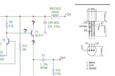
I want to replace BC517 with 2SK170 but I don't know the orientation of the pin, I mean where is conection drain pin,gate pin, source pin? , (example : source pin to both of R6 and T2 ???? etc )
Tks all
regards
aquar
martin clark said:I think the problem is the capcitance multiplier befor eteh LM317.
As you try to draw more load current then the base current increase through R1 means the voltage across teh BC547 increase. I think when you have your sulzer reg running, the LM317 is dropping-out (insufficient voltage hedroom)to operate. If this is the case (less than 3.0v across the LM317) then consider removing the cap multiplier, or maybe use a darlington transistor here instead.
Measure the voltages before the BC547 and before the LM317 to check this... what is +Vin , when fully loaded?
Hi Martin,
Sory for late reply, I dicided to postphone (temporary) this project, I have noted your advise and will do it someday.
Now, I just installed new filter discrete to replace opamp (OPA 132/OPA 627)....tks Ray,tks Jaap for schematic and layout.
After a few hour running I got impression that sound tobecome superb, big and bold, more natural and more detail bass. The resonance of every musics stuff more liveness, I found big improvement to replace opamp with this filter.
Litlle question:
I want to replace BC517 with 2SK170 but I don't know the orientation of the pin, I mean where is conection drain pin,gate pin, source pin? , (example : source pin to both of R6 and T2 ???? etc )
Tks all
regards
aquar
Attachments

Glenn2 said:
Would a 0.5R resistor (two 1R in parallel) between reg and DAC be better than just a wire? I'm not sure how critical the output impedance is in this scenario.
I could insert the series resistor in the +ve wire from the board.
I would advise against fitting resistors.
They adversely affect the regulation.!
Andy
- Home
- Source & Line
- Digital Source
- Marantz CD63 & CD67 mods list