martin clark said:Yes it is - sorry, I addressed my response above to aquar for some reason.
I was gonna say but...

The way a PWM output works is basically toggling between its supply rails isn't it? Doesn't that equate to zero power-supply rejection also?
If so, then the drop across my series 0.5R caused by the supply current flowing through it (a mA or two of PWM pulses) will be directly coupled to the output.... but will be common-mode and rejected by the differential filter circuit... I think so maybe not an issue (assuming good common-mode rejection of following circuit).
I still can't decide if the 0.5R should be there or not!
Sod this, I'm going down the pub!😀
If so, then the drop across my series 0.5R caused by the supply current flowing through it (a mA or two of PWM pulses) will be directly coupled to the output.... but will be common-mode and rejected by the differential filter circuit... I think
so maybe not an issue (assuming good common-mode rejection of following circuit). I still can't decide if the 0.5R should be there or not!
Sod this, I'm going down the pub!😀
More weight in the bass, please
Hi everyone, I'm a newbie to posting, but can a few people give me their opinions on how bypassing the HDAMs and/or DC blocking caps improves the bass, please?
With the help of a friend and after reading this thread a couple of times, together with the tntaudio and acoustika articles, my CD63 is transformed in terms of detail and noise level - my wife listened to a new Elgar CD the other day and said "This is a really good recording - you can hear all the instruments", but I know all the CD's sound better now - apart from the ones that are now unlistenable! It reminds me more of listening to a mastertape than listening to a CD. And really fussy about interconnects.
So far we have a CD63 MkII KIS with chassis, lid and strut damped with Tetrasyl, the feet replaced with wooden cones, the mains cable shortened and terminated with a HQ IEC socket fed by a hefty shielded cable. The IC's are damped with a sandwich of ERS RF barrier paper and Tetrasyl and more ERS sheet over the mains Tx and behind the display panel.
The 7812 and 7912 regulators are directly replaced with Audiocom Superregulator2s, the 7805 with an Invisus PPR1 and the crystal with a Superclock3. The opamps are replaced with LM4562s and the decoupling (?) caps with BG standards. And that's it so far.
It's had about 30 hours listening so far and is getting better as it runs in, but I suspect the bass is going to sound more like a Pink Triangle than an Ariston RD11 when the running in is complete (50 hours?).
I would like to know if I should bypass/remove either the HDAMs and/or the the output blocking caps to get more weight in the bass, or if these mods simply make the bass faster and cleaner. Any thoughts, please? BTW I don't want to keep using up my good friend's evenings and will be doing this myself, and I am completely new to soldering..., so low risk is important too!
Re: More weight in the bass, please
Hi Micky, and welcome to this great thread!
Firstly - wow, you've done some great mods. My briefest advice to you would be that the HDAM bypass will reduce the apparent bass weight. It will, however, improve the subjective clarity and timing of the bass.
Bypassing the DC blocking caps will, without reducing the bass weight, improve the clarity again. This is a fantastic free and easy upgrade. The bass gains some real ability to follow complex passages and sounds very emphatic.
Additional transformers to power DAC, decoder and servo chips will improve the bass weight A LOT. At least it did for me.
For the icing on the cake you'll want to reclock your servo. This improves detailing and treble treble clarity most of all.
Hope that helps.
Simon
micky127 said:I would like to know if I should bypass/remove either the HDAMs and/or the the output blocking caps to get more weight in the bass, or if these mods simply make the bass faster and cleaner. Any thoughts, please? BTW I don't want to keep using up my good friend's evenings and will be doing this myself, and I am completely new to soldering..., so low risk is important too!
Hi Micky, and welcome to this great thread!
Firstly - wow, you've done some great mods. My briefest advice to you would be that the HDAM bypass will reduce the apparent bass weight. It will, however, improve the subjective clarity and timing of the bass.
Bypassing the DC blocking caps will, without reducing the bass weight, improve the clarity again. This is a fantastic free and easy upgrade. The bass gains some real ability to follow complex passages and sounds very emphatic.
Additional transformers to power DAC, decoder and servo chips will improve the bass weight A LOT. At least it did for me.
For the icing on the cake you'll want to reclock your servo. This improves detailing and treble treble clarity most of all.
Hope that helps.
Simon
More weight in the bass, please
SimontY, thank you for your comments. If I understand you correctly, removing the DC blocking caps will give me what I am after with minimal risk of lifted tracks, etc. I will try that first.
SimontY, thank you for your comments. If I understand you correctly, removing the DC blocking caps will give me what I am after with minimal risk of lifted tracks, etc. I will try that first.
Re: Re: good by opamp
Hi Simon,
You will not regret with the result, ofcourse you will do a litlle hard job to fit it.
regards
aquar
SimontY said:
Fantastic news aquar! It inspires me to hurry up and do mine...
Simon
Hi Simon,
You will not regret with the result, ofcourse you will do a litlle hard job to fit it.
regards
aquar
Re: Re: Re: good by opamp
Yes, it's very good for minimal risk. Just unsolder and remove the 4 caps. Then solder in a wire link to bridge the gap created by the removal. With the mods you've already done I expect it will be rather noticeable.
Hi aquar,
Well I made a small start. I filed the pcb down to the bare minimum last night. I also polished and treated with Deoxit D5 the copper surface. I need to order my transistors and resistors now. I have the small caps and coils.
Simon
micky127 said:SimontY, thank you for your comments. If I understand you correctly, removing the DC blocking caps will give me what I am after with minimal risk of lifted tracks, etc. I will try that first.
Yes, it's very good for minimal risk. Just unsolder and remove the 4 caps. Then solder in a wire link to bridge the gap created by the removal. With the mods you've already done I expect it will be rather noticeable.
aquar said:Hi Simon,
You will not regret with the result, ofcourse you will do a litlle hard job to fit it.
regards
aquar
Hi aquar,
Well I made a small start. I filed the pcb down to the bare minimum last night. I also polished and treated with Deoxit D5 the copper surface. I need to order my transistors and resistors now. I have the small caps and coils.
Simon
I stuffed the first 18 components into my discrete board last night. It's looking lurvely! The box-shaped polystyrene 4.7n caps were very difficult to fit, and by enlarging the output cap holes I made that area a bit messy. I'll upgrade them later but for now I've used 22uF/63v WIMA film caps.
Need to buy my Kiwame resistors and the transistors to get any further now..
Jaap, if you're there, those diodes were a bit funny, in that they're not marked on your diagram. I think I've got em right though, the cathodes point towards the -12v input.
Simon
Need to buy my Kiwame resistors and the transistors to get any further now..
Jaap, if you're there, those diodes were a bit funny, in that they're not marked on your diagram. I think I've got em right though, the cathodes point towards the -12v input.
Simon
rowemeister said:Turn laser over - you will see two torque screws. It's usually the one at the rear of the laser.
Turn it 1/4 turn and test. If its worse put it back to where it was then turn 1/4 turn the other way. If there is an improvement you know you are close and try another 1/4 turn. If there is no difference the laser is crap.
Little adjustment is needed - use your ears and listen to the laser to hear if it sounds crisp and healthy when scanning.
Brent
Brent you're a star. I tried the rear screw and in the best position it was a little better but still not cured. Tried the other screw (1/4 turn clockwise) and now it is cured.
Nice one.
So after wasting my time with two dud VAM1202s from Grandata, I have the original CDM12.1 working perfectly!
I'll still send the other one back to them for a replacement, and just hope I don't have to use it! Also, my spare 63 has a new and working VAM1202 so I have that as a backup too. 🙂
A sad departure
Hi,
Even though I'd sworn that I wouldn't go near the opamp/dac area again due to the fragile nature of previous mods (lots or point to point wiring to repair lifted tracks etc.) I succumbed to the power of the dark side and decidec to fit some blackgates in there.
I'd intended that this would be the last mod I made and, sadly, this turned out to be very true.
After several more lifted traces (and many bodged recovery attempts) death was pronounced at 12:56 today. A sad loss of a nice sounding extensively modded (and expensive) 67.
It will be much missed.
Yours in mourning
Pete
Re: A sad departure
Oh no, another stiff! Terrible news Peter!
Chivvyp said:Hi,
Even though I'd sworn that I wouldn't go near the opamp/dac area again due to the fragile nature of previous mods (lots or point to point wiring to repair lifted tracks etc.) I succumbed to the power of the dark side and decidec to fit some blackgates in there.
I'd intended that this would be the last mod I made and, sadly, this turned out to be very true.
After several more lifted traces (and many bodged recovery attempts) death was pronounced at 12:56 today. A sad loss of a nice sounding extensively modded (and expensive) 67.
It will be much missed.
Yours in mourning
Pete
Oh no, another stiff! Terrible news Peter!
Re: A sad departure
The A&E department is open - did you blow up the DAC? Anything else is repairable unless the pins fell off it!
Was there lots of smoke?
I think you may be able to clock the the decoder instead of the DAC and still use the S/PDIF or hook up the I2S to another DAC (not sure about that).
You have my sincerest condolences by the way.
Chivvyp said:Hi,
Even though I'd sworn that I wouldn't go near the opamp/dac area again due to the fragile nature of previous mods (lots or point to point wiring to repair lifted tracks etc.) I succumbed to the power of the dark side and decidec to fit some blackgates in there.
I'd intended that this would be the last mod I made and, sadly, this turned out to be very true.
After several more lifted traces (and many bodged recovery attempts) death was pronounced at 12:56 today. A sad loss of a nice sounding extensively modded (and expensive) 67.
It will be much missed.
Yours in mourning
Pete
The A&E department is open - did you blow up the DAC? Anything else is repairable unless the pins fell off it!
Was there lots of smoke?
I think you may be able to clock the the decoder instead of the DAC and still use the S/PDIF or hook up the I2S to another DAC (not sure about that).
You have my sincerest condolences by the way.
Re: Re: A sad departure
Yep, lost a pin from the dac and several of the dac pads from the board. Pretty ham fisted really.

Don't really think resuscitation is possible. Maybe it can be cryogenically frozen until science finds a cure!
Regards
Pete
Glenn2 said:
The A&E department is open - did you blow up the DAC? Anything else is repairable unless the pins fell off it!
Was there lots of smoke?
I think you may be able to clock the the decoder instead of the DAC and still use the S/PDIF or hook up the I2S to another DAC (not sure about that).
You have my sincerest condolences by the way.
Yep, lost a pin from the dac and several of the dac pads from the board. Pretty ham fisted really.
Don't really think resuscitation is possible. Maybe it can be cryogenically frozen until science finds a cure!
Regards
Pete
Re: Re: Re: A sad departure
Oh dear. If the DAC is still powered on the digital side and still has the clock (i.e., if the player still plays discs in some way) you could strap a TDA1543 to the I2S lines and have a play with Non-OS. I did - sounded good but I preferred the built-in DAC.
If this is the case you can have my TDA1543 board I made (with chip). Takes a minute to solder in and you don't have to take the board out.
If the DAC/player is not functioning at all then probably no hope...
Chivvyp said:
Yep, lost a pin from the dac and several of the dac pads from the board. Pretty ham fisted really.
Don't really think resuscitation is possible. Maybe it can be cryogenically frozen until science finds a cure!
Regards
Pete
Oh dear. If the DAC is still powered on the digital side and still has the clock (i.e., if the player still plays discs in some way) you could strap a TDA1543 to the I2S lines and have a play with Non-OS. I did - sounded good but I preferred the built-in DAC.
If this is the case you can have my TDA1543 board I made (with chip). Takes a minute to solder in and you don't have to take the board out.
If the DAC/player is not functioning at all then probably no hope...
I suppose a 53/63 is cheap enough on eBay.
Especially if you can grab one with a dodgy laser.
Especially if you can grab one with a dodgy laser.
or
use it as a transport
and/or
i2s or SPDIF into this
http://www.diyaudio.com/forums/showthread.php?s=&threadid=79456
allan
use it as a transport
and/or
i2s or SPDIF into this
http://www.diyaudio.com/forums/showthread.php?s=&threadid=79456
allan
SimontY said:I stuffed the first 18 components into my discrete board last night. It's looking lurvely! The box-shaped polystyrene 4.7n caps were very difficult to fit, and by enlarging the output cap holes I made that area a bit messy. I'll upgrade them later but for now I've used 22uF/63v WIMA film caps.
Need to buy my Kiwame resistors and the transistors to get any further now..
Jaap, if you're there, those diodes were a bit funny, in that they're not marked on your diagram. I think I've got em right though, the cathodes point towards the -12v input.
Simon
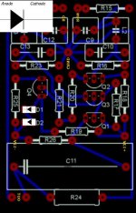
Hi Simon,
Diodes, here pic maybe can help you and be carefull with orientation of Q4, recheck again with other datasheet.
Regards
aquar
Attachments
Re: Re: Re: Re: A sad departure
Thanks for the kind offer. I think the digital and clock lines will still be ok but, to be honest, that whole area is so fubar I can't really be bothered to try to reconnect it all to check. I've (obviously) got all the mod parts still so I'll look out for a new machine on ebay over the coming months and then transplant them.
In fact I've been thinking of moving to computer based playing for a while and this has stimulated me in that direction. I've spent the weekend starting on copying all my cds and I've also put out an order for a USB DAC module to play with.
Regards
Pete
Glenn2 said:
Oh dear. If the DAC is still powered on the digital side and still has the clock (i.e., if the player still plays discs in some way) you could strap a TDA1543 to the I2S lines and have a play with Non-OS. I did - sounded good but I preferred the built-in DAC.
If this is the case you can have my TDA1543 board I made (with chip). Takes a minute to solder in and you don't have to take the board out.
If the DAC/player is not functioning at all then probably no hope...
Thanks for the kind offer. I think the digital and clock lines will still be ok but, to be honest, that whole area is so fubar I can't really be bothered to try to reconnect it all to check. I've (obviously) got all the mod parts still so I'll look out for a new machine on ebay over the coming months and then transplant them.
In fact I've been thinking of moving to computer based playing for a while and this has stimulated me in that direction. I've spent the weekend starting on copying all my cds and I've also put out an order for a USB DAC module to play with.
Regards
Pete
aquar said:Hi Simon,
Diodes, here pic maybe can help you and be carefull with orientation of Q4, recheck again with other datasheet.
Regards
aquar
Thanks a lot Aquar, that confirms I've soldered them in correctly. My transistors have arrived now so I'll solder those in this evening.
Thanks
Simon
- Home
- Source & Line
- Digital Source
- Marantz CD63 & CD67 mods list