Her names are Mara Elise, born December 1st, 13:34.
I'm a happy man!!

Congrats, all the best.
P.S Sleep when she does LOL
That's your greatest success Ray! =) So cute!
Yes, I think she will probably exploit that when she's older 😀
Congratulations Ray 😉
December will not be cheap from now on 🙂
P.S Simon already has a pink iron
Brent
Now, now, behave in front of a lady 😀
Thanks Brent. All hope for new results on your C2 clock is now gone, as i'm free from work 'till the 4th of januari

You may blame the little one

Bottle-fed I hope? (as a valve/tube man...
Judging by the satisfied look on the face of my daughter, my wife's breasts taste very good, so that's minus one point for me. But just wait when I get her to solder her first resistor...

Congrats, all the best.
P.S Sleep when she does LOL
Thanks, the nights are broken (well, it's only been three so far...) but she's very sweet and quiet after her nightly meals
 , so luckily we get a few hours sleep in between!
Regards,
Ray
I see some of you have 20+ regs in the cd63. Since the biggest improvement on mine yet was replacing the 12v+/- rails (analog section) with lm317/337's, I am looking to for other regulator-related opportunities.
Where did you put them?
Where did you put them?
Bottle-fed I hope? (as a valve/tube man...)
Regards to the track re-routing;
1) Remove U234, U161 and U237 shown in red to isolate the drivers from the raw supplies.
2) Insert -ve reg at U234 (use holes as input and output)
3) Insert +ve reg at either U161 or U237 (use holes as input and output
4) Connect blue wire as shown (you can use any colour 🙂 )
Simples.
Do you need to run a wire to ground from the ground pins also? 😕
Hi guys, how are things over here?
Been away for a while for more important matters. Here's the result: 😀
Congratulations Ray.
All the Best.
Pink soldering iron for first birthday is likely a sure thing.
Steve
Congratulations on your new addition to the family Ray.
Lee.
Congratulations Ray.
All the Best.
Pink soldering iron for first birthday is likely a sure thing.
Steve
Thanks for your kind words guys. She's a lively little lady, we found that out last night 😀
If it has any more of my character, we're in for quite a party!
Ray
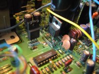
HF regulator
Hi,
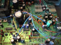
Here's a pic showing where to insert a regulator for the HF amp. R505 (100R) comes out and reg goes in. C504 is worth upgrading too, I used an os-con SEPC as Lee recommended to me. This mod seems to improve all areas just a little bit, but it's probably not the biggest one, more a finishing touch.
The pic also shows the three decoder regs I put in this player (Steve's). It's easier to do just two regs (R508 - digital pins and R511 - analogue pin), 3 was a little bit faffy and probably gains very little! Even putting lowly 7805 regs on the decoder makes a very noticeable improvement - a must for anyone handy with a soldering iron.
Simon
Hi,
Here's a pic showing where to insert a regulator for the HF amp. R505 (100R) comes out and reg goes in. C504 is worth upgrading too, I used an os-con SEPC as Lee recommended to me. This mod seems to improve all areas just a little bit, but it's probably not the biggest one, more a finishing touch.
The pic also shows the three decoder regs I put in this player (Steve's). It's easier to do just two regs (R508 - digital pins and R511 - analogue pin), 3 was a little bit faffy and probably gains very little! Even putting lowly 7805 regs on the decoder makes a very noticeable improvement - a must for anyone handy with a soldering iron.
Simon
Attachments
Last edited:
High all yes simon these last mods have made the player great realy nice depth of image and smoother all round sound
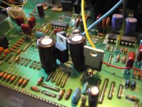
Servo regulators: how-to
Sorry if this mod's been posted before with pics, but I can't remember with the thread being so long!
To feed the servo chip cleaner power, cut R122 (digital feed) and R123 (analogue feed) and plumb in a 7805 for each (or share one, it will still give good gains).
Pin 3 of the 7805 is output so solder it to the resistor leg you left in place (you don't even need the board out for this work), pin 2 is ground - solder this to the PCB top (scratch the lacquer off with a fibreglass pencil) and bend the input pin (pin 1) back and feed it with a wire tapped from C813 ("+10V"). U236 or U237 is good for soldering your power wire to, but may need a clean-up with the fibre pen to make the solder flow easily.
Attachments
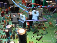
Focus/radial driver op-amp
Here's Q106, which the service manual tells me does "radial" and "focus". That sounds important to me 🙂
This player didn't like -8V here (reg inserted in-line with U149) so I restored it, as you can see in the picture. I left the 7808 in place - perhaps it's useful to see how it's done. The negative regulator has a different pin-out so don't just wire that up the same - make a drawing of it and refer to it as you solder it up, and check it after you solder it. Otherwise it'll probably go bang on power-up 😱
It's 100% happy with just 3 of the 6 voltage rails on the drivers regulated. I will do wire jumpers from the other 7808/7908 and regulate QM01 too.
Attachments
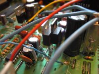
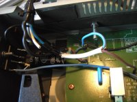
Here's where you can easily feed Q105 (sled/laser diode driver). My pics don't show it clearly but it's the same as with Q106, except you're cutting out resistors rather than a wire link.
ps - that blue wire feeds the analogue regs on the servo, decoder and DAC. The others currently run off the big 10V rail.
ps - that blue wire feeds the analogue regs on the servo, decoder and DAC. The others currently run off the big 10V rail.
Attachments
Last edited:
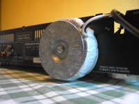
These pics show the easiest way to add another transformer and power supply (or supplies) to the player. If you position it just right a fairly large toroid can be bolted to the back without affecting the lid fitting properly or causing other clearance issues.
I hope this helps some of you.
Simon
I hope this helps some of you.
Simon
Attachments
Do you need to run a wire to ground from the ground pins also? 😕
Yes, to U274 is the best place.
When I said insert regulators there, by regulator I mean regulator circuit, not just the three-legged item itself.
You at least need to add output decoupling capacitors, 100uF-470uF/16V is my recommendation, in addition to ground connections.
I always use a little bit of veroboard containing LM317/337, voltage setting resistors, decoupling caps.
Last edited:
Simon,
very nice that how-to series, nice pics!
Grofus, as Glenn said it's handy to work on protoboard.
http://www.diyaudio.com/forums/digi...ntz-cd63-cd67-mods-list-1321.html#post1924236
Matthieu
very nice that how-to series, nice pics!
Grofus, as Glenn said it's handy to work on protoboard.
http://www.diyaudio.com/forums/digi...ntz-cd63-cd67-mods-list-1321.html#post1924236
Matthieu
Cheers.
For a beginner I think it's a bit much to be using separate boards and extra caps. It's much easier just to wire the regs in directly. The output caps are already on the board for you, but I usually add the odd extra input cap to make sure the regulator is happy.
Simon
For a beginner I think it's a bit much to be using separate boards and extra caps. It's much easier just to wire the regs in directly. The output caps are already on the board for you, but I usually add the odd extra input cap to make sure the regulator is happy.
Simon
The output caps are already on the board for you....
Not if you leave the resistors in the circuit, which is a good idea as it isolates the servos drivers from each other. These form RC filters with the caps at the drivers.
But basically, if you use the insertion points I suggested, you definitely need the output caps.
I think the big benefit of all of this is actually keeping the servo noise away from the rest of the player, i.e. less of it on the raw 10V supply for the rest of the player.
But if you are using the resistor points to insert individual regulators - so the existing caps are on the reg's output - then no you don't need any more caps.
Last edited:
Simon, thanks for the detailed info on fitting the regs. Glenn and Malefoda, thanks also.
I think I need to gen up on basic electronics, so I can "understand", rather than just copy. Anyone recommend a book ? Never realised how addictive this is! Cheers Steve
I think I need to gen up on basic electronics, so I can "understand", rather than just copy. Anyone recommend a book ? Never realised how addictive this is! Cheers Steve
Last edited:
Maybe have a look at:
Ray's Audio Page
then:
Using 3-pin regulators off-piste: part 1
and Simple Voltage Regulators Part 1: Noise - [English]
Ray's Audio Page
then:
Using 3-pin regulators off-piste: part 1
and Simple Voltage Regulators Part 1: Noise - [English]
- Home
- Source & Line
- Digital Source
- Marantz CD63 & CD67 mods list