You shouldn't have ground loop problems inside the box, and YES the best way of transmitting digital signals for ultimate signal integrity and minimising system noise is for each signal to have its own return path in close proximity... This is why you should have a ground plane adjacent to your digital signals, unbroken and without slots....
http://www.ultracad.com/articles/slots.pdf
Having a signal go down a cable without its own return is like having a slot in the ground plane...
This is the best practice for digital signals. How necessary it is depends on how far you want to go, speed of the signals (determined by the signals rise time), EMC requirements, noise margins etc. If you are unsure always transmit digital signals as a pair, signal and its return.
More info on signal flow..
http://www.x2y.com/filters/TechDay0...log_Designs_Demand_GoodPCBLayouts _JohnWu.pdf
Hi,
thx Slit in Groundplane as figurative equivalent was the crux. Thanks. I allready knew that groundplanes are supposed to give a (proximately close) low resistance return path. But the separated signal lines confused me - because it contradicts with the idea of one Single Ground-to-Ground connection (if you have several pcbs).

thx Slit in Groundplane as figurative equivalent was the crux. Thanks. I allready knew that groundplanes are supposed to give a (proximately close) low resistance return path. But the separated signal lines confused me - because it contradicts with the idea of one Single Ground-to-Ground connection (if you have several pcbs).
I work on many designs that have multiple boards and multiple ground connections, the one ground if for protective earth connections, between boards where you have multiple signals you will get multiple ground connections... This can be a problem sometimes and if it is usually adding a very thick ground wire between boards solves the problem...
Have a look at Tony Waldrons EMC rants, regarding multiple grounds, it is the same for PCBs only on a smaller scale, in a multiple PCB system you will get different ground connections, it is controlling where your ground currents flow that is the solution.
Tony Waldron's EMC ranting and ravings
Have a look at Tony Waldrons EMC rants, regarding multiple grounds, it is the same for PCBs only on a smaller scale, in a multiple PCB system you will get different ground connections, it is controlling where your ground currents flow that is the solution.
Tony Waldron's EMC ranting and ravings
Grounding can be an emotive and perplexing subject, there is no easy and quick answer and every system has its own problems and solutions.
Some more list of links, the first is probably most applicable in your case, has Jenson transformer notes on this.....
The last is also of interest.
The PCB related links is something I threw together as a basic primer for those new to PCB design (on and EDA thread) who always ask where do I start.... so some is relevant some may not be, but some interesting sites.
Attachments
No problem, I have 5+gig of documentation related to PCB design, signal integrity, EMC etc. that I have collected over the years. I believe in passing it on to as many interested in PCB design as possible, as in the UK it does not get the status it deserves.🙂
Opamp rolling combination
:: Art's Corner @ Marantz CD63 KI Upgrade - Modifications
Very interesting and I agree with almost everything written in this text especially when it comes HDAM again I returned it back.
:: Art's Corner @ Marantz CD63 KI Upgrade - Modifications
Very interesting and I agree with almost everything written in this text especially when it comes HDAM again I returned it back.
Hi Everyone,
Firstly I'd like to say thanks to all the contributors to this massive thread - I have a CD63 mkII KI Signature that I've just started to mod using the info on this thread as my source of inspiration. So far I've done the following mods:
1) Removed the dc blocking caps after checking the offset (30-35mV on my player) - huge improvement in bass particularly, much more relaxed and natural sounding.
2) Used bitumen damping sheets throughout the case and on the cd mechanism - a more subtle improvement but resolution has definitely improved
3) Fitted IEC mains socket and run an earth wire to the star earth point at the output RCA's - this lowered the noise floor and gave a better sense of space to the reproduction
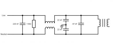
4) Added some input mains filtering on the board before the transformer; this is the mod I need some help with! I've attached the schematic below, basically I made this from parts taken from an old pc power supply so I don't know the inductance value for the common mode filter - the original supply was rated at 250W. The X class caps across the line are MKP type, the Y class caps are ceramic. It works and has decreased the noise floor still further and also seems to have increased the depth of the soundstage, BUT it's also killed the dynamics completely and the bass timing has softened so it now sounds blurred in places.
Obviously I'd like to keep the benefits of this filter without the downsides but I don't know where to go with this. At a guess I'd say the common mode filter is the problem and it's restricting input current too severely, but that's just my guess... any input greatly appreciated🙂
Firstly I'd like to say thanks to all the contributors to this massive thread - I have a CD63 mkII KI Signature that I've just started to mod using the info on this thread as my source of inspiration. So far I've done the following mods:
1) Removed the dc blocking caps after checking the offset (30-35mV on my player) - huge improvement in bass particularly, much more relaxed and natural sounding.
2) Used bitumen damping sheets throughout the case and on the cd mechanism - a more subtle improvement but resolution has definitely improved
3) Fitted IEC mains socket and run an earth wire to the star earth point at the output RCA's - this lowered the noise floor and gave a better sense of space to the reproduction
4) Added some input mains filtering on the board before the transformer; this is the mod I need some help with! I've attached the schematic below, basically I made this from parts taken from an old pc power supply so I don't know the inductance value for the common mode filter - the original supply was rated at 250W. The X class caps across the line are MKP type, the Y class caps are ceramic. It works and has decreased the noise floor still further and also seems to have increased the depth of the soundstage, BUT it's also killed the dynamics completely and the bass timing has softened so it now sounds blurred in places.
Obviously I'd like to keep the benefits of this filter without the downsides but I don't know where to go with this. At a guess I'd say the common mode filter is the problem and it's restricting input current too severely, but that's just my guess... any input greatly appreciated🙂
Attachments
Could someone recommend me an Opamp for my modded Marantz CD53? LME49720 sounds amazing, though I'd like more lows (100-500Hz range I'd say, bass is good). The only other Opamp I've tried is OPA2132 and it sounds boring, has overblown bass and worse lows than the LME49720.
Hi Everyone,
...
4) Added some input mains filtering on the board before the transformer; this is the mod I need some help with! I've attached the schematic below, basically I made this from parts taken from an old pc power supply so I don't know the inductance value for the common mode filter - the original supply was rated at 250W. The X class caps across the line are MKP type, the Y class caps are ceramic. It works and has decreased the noise floor still further and also seems to have increased the depth of the soundstage, BUT it's also killed the dynamics completely and the bass timing has softened so it now sounds blurred in places.
Obviously I'd like to keep the benefits of this filter without the downsides but I don't know where to go with this. At a guess I'd say the common mode filter is the problem and it's restricting input current too severely, but that's just my guess... any input greatly appreciated🙂
Hi,
I doubt that a few uH of inductance in the mains line will hinder the current flow, I mean, mains frequency is just 50Hz so the extra impedance will be far below 1 ohm. The peak current demanded by the player will be provided by the large buffer caps in the power supply.
If you inserted two Y-type caps from both mains lines to the chassis, you should try grounding the chassis.
Regards,
Ray
Maybe AD8620 will be the right one. I like it a lot, though it can be unforgiving 🙂
Is that SMD only? Can't find a through-hole version on Mouser.
Also, what difference would changing the 220uf capacitors at the power pins make? I still haven't replaced those. Was thinking Nichicon FG of the same value. Will that improve the lower midrange in any way? Would a higher capacitance make a big difference?
If by this you mean you have the outer gnd of the rca plugs connected directly to mains safety earth, this isn't ideal as it means you have your sensitive low level output signal directly wired to loads of other things on your mains supply with no filtering for noise.3) Fitted IEC mains socket and run an earth wire to the star earth point at the output RCA's - this lowered the noise floor and gave a better sense of space to the reproduction
The cd player originally only has a 2 wire mains connection with no connection for mains earth.
By all means have an EIC plug, but connecting the mains earth to the chassis or rca plugs may cause you more issues than it solves.
Thanks for that - both the Y caps run to a second earth point I made on the power board which is directly connected to the earth on the mains socket and the star earth point on the main pcb. I assume the chassis will be grounded via the RCA sockets on the backplate.
The reservoir caps are the original ones, so maybe they are not up to spec after nearly 20 years... I am aiming to replace these with the values suggested in your mods list so perhaps I'll re-visit this input filter once the new caps are in place.
In the meantime I'll try to troubleshoot this by bypassing or disconnecting each component in turn to see if I can isolate the issue.
I did wonder about the possibility of getting extra noise via the earth connection or even an earth loop hum, but earthing by itself didn't seem to cause problems.
Last edited:
Is that SMD only? Can't find a through-hole version on Mouser.
Yes, you need a couple of those:
SO8 to 8-pin DIP Adapter (p/n 970601A)
or similar.
How about trying the good old NE5532
Yes, you need a couple of those:
SO8 to 8-pin DIP Adapter (p/n 970601A)
or similar.
How about trying the good old NE5532
I will order a couple other Opamps to try (OPA2604, OP275, NE5532, LME4986).
Also, does it make any difference whether the caps around the Opamps are 220 or 470uf?
I will order a couple other Opamps to try (OPA2604, OP275, NE5532, LME4986).
Also, does it make any difference whether the caps around the Opamps are 220 or 470uf?
Question is - can you hear any difference ?
My answer - no 🙂
Hey guys, a little troubleshooting needed...
I've been having intermittent trouble with my player for a while with a blank display and spinning disk.
I tracked it down before to the new 5v regulator I had put in for the decoder and replaced it which seemed to fix the problem. But now I see the same again, so I checked the output of the 5v regulator and it was real low as if it had a big load, so I pulled the regulator and checked continuity across it's mounting points on the board (actually in the original C512 position) and I get continuity 🙁 SO I pulled the electrolytic at C511 out to see if it had shorted somehow and that part is fine, but with this removed too I am getting continuity between gnd and the 5v input for the decoder.
Can this be anything other than a fried decoder chip? I can't see any obvious physical issues that would cause this....
thanks,
James
- Home
- Source & Line
- Digital Source
- Marantz CD63 & CD67 mods list