Hi, I was just going to put my regs back in when I realized something. The power supply at the servo and decoder is 5v (r508, r510, r122 and r123). The regs need 7-8 volts minimum to function don't they? Do I need to hard wire them from the toroids? P.S. It would be nice to trace the circuit myself but I cannot follow the lines using Ray's copy of the service manual. Does anyone have a better scan? Henry
Hi, I am guessing the answer is I should use something like U218 for the 12v+ supply. But I am disappointed because the mini boards I bought have two pins that secure them nicely into the holes provided by the removed resistors😱. With only one pin holding them in I am worried the regs will be held in too loosely. Does anyone have advice on how to hold the regs in place? Henry
Hi,
You do need some headroom on the regs for them to work, 7-8v for a 5v reg should be fine normally.
If you take the voltage direct from the toroids you will need a diode bridge etc. to convert the ac coming from the toroids to dc though.
Where are you taking the v from at the moment, normally if you take the v from the input to the original 5v regs you should have enough headroom.
Regards
Pete
Guys, does anyone have any experience of adding multiple TX's versus using the stock TX and lots of additional regs to isolate the different chips? (CD57/67 btw)
Also I'd like to understand the rationale around changing C108,9,10 & C125. Particularly the increase in value of C109 from 22n to 100n.
I ask because I recently traced an issue I had back to my PS C110. I had to replace it to make the CDP read discs but the only 47p cap I had to hand was a silver mica. I'd just upgraded all the supply caps around the decoder but to me it now sounds more muddy than before I'd touched the decoder section. Since all the mods to that section (except the caps mentioned above) are related to decoupling 5V rails, I was wondering if C110 etc can affect the tone or clarity of the HF signal before it it received by the decoder?
In addition to replacing C115 etc with 100n as per Ray's mods, I bypassed them with 47uF electrolytics from Maplin (like Bobswire). These couldn't degrade the audio quality surely?
Lots of questions....sorry!
Henry, I installed regs similar to you but soldered the ground leg to the top of the ground plane of the board so that the regs are stood on two legs at least.
I'd tried running wires from the ground pins of all the regs to a central star point but couldn't hear any difference from using the ground plane.
I'd tried running wires from the ground pins of all the regs to a central star point but couldn't hear any difference from using the ground plane.
Hi gents,
having troubles again with that f***ing CD player I put things under your minds in case someone has a clue in order to fix it. It sounds much better than the Denon DVD-3910 I prepare for transport, so want to keep my Marantz as long as possible.
First issue was a "out of sync" Servo as the added flipflop clock had a solder joint problem. It was going full sled and "tic tic tic tic..." at the end of the gear like crazy. Touching the clock/moving the CDP brought it back to service, or I had to switch off the player and then on.
Then changed clock: OK but an error 02, focus.
Test the CDM12 laser seemed weak, used a spare VAM (of unkown origin I must say) solved that error 02, so I've closed the lid.
But then it devlopped new symptom ; now and then -wich does not help fixing- it spinned the disc weakly, like when you use the whole VAM and disc is not clamped well, a kind of "sccwwiit swwwit sound", (about clamp, I've just used the VAM's laser). When it does that too much the player stopped playing and goes back to "stop" position. Play and it plays again until noise, skipping and stop.
I am right now waiting for 7824 for a dedicated PSU for the driver's clock and an Philips CD711 for the whole CDM12.
And tonight, colder than the other days, I went back home hoping for some music between the skippings. Hell on Earth, tonight I only have an error 2...
Too much for me to think of what to do, seems my player is cursed. Anyone to point me what to look at?
Matthieu
Hi Pete and pjoliver,
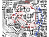
I tried putting regs onto the servo but I think I blew the chip. I cut u182, u185, u186 to remove the 5V feed to the servo (see attached). I had to jumper from u182 to 185 and u186 to supply 5v to the other parts of the board. I then jumpered in +15V into the other leg of u182 from u161 to supply the 5V regs that I put in r508 and r511. I also cut the trace between r511 and c513 and jumpered 5v from c512 to c513 so that both digital pins (15 and 44) have the same 5v supply. (I grounded the regs to the nearest ground point).
I think this would have worked except I ended up connecting the regs to u162 instead of u161 by accident . This provided the regs with -15V and blew the tants on the regs. I have fixed the regs and they are working well now, but the transport is erratic and refuses to work properly. I think the -15V blew the servo chip before I managed to switch it off. Now I don't know whether to get another CD63 from ebay and use the board, or try to replace a 44 pin SMD chip. Hmmmmm...
Henry
I tried putting regs onto the servo but I think I blew the chip. I cut u182, u185, u186 to remove the 5V feed to the servo (see attached). I had to jumper from u182 to 185 and u186 to supply 5v to the other parts of the board. I then jumpered in +15V into the other leg of u182 from u161 to supply the 5V regs that I put in r508 and r511. I also cut the trace between r511 and c513 and jumpered 5v from c512 to c513 so that both digital pins (15 and 44) have the same 5v supply. (I grounded the regs to the nearest ground point).
I think this would have worked except I ended up connecting the regs to u162 instead of u161 by accident
. This provided the regs with -15V and blew the tants on the regs. I have fixed the regs and they are working well now, but the transport is erratic and refuses to work properly. I think the -15V blew the servo chip before I managed to switch it off. Now I don't know whether to get another CD63 from ebay and use the board, or try to replace a 44 pin SMD chip. Hmmmmm...Henry
Attachments
Last edited:
Now I don't know whether to get another CD63 from ebay and use the board, or try to replace a 44 pin SMD chip. Hmmmmm...
Henry
I wouldn't even consider trying to replace a 44 pin smd chip unless you're very, very experienced at soldering and have some good equipment desoldering supplies etc. (or you're not worried about destroying the board - given it's useless at the moment anyway 🙂 )
I once did the dac chip in a 67 and ended up with broken traces to 4 or 5 pins, I managed to recover the player with some point to point wiring but I doubt I'd bother again if I could get hold of a new board easily.
Regards
Pete
Henry
Could you describe the erratic behavior of the transport? Are you getting any error codes in service mode?
Have you checked your voltages on the servo chips? I'd do some fault finding with your multimeter before you decide to do anything.
Could you describe the erratic behavior of the transport? Are you getting any error codes in service mode?
Have you checked your voltages on the servo chips? I'd do some fault finding with your multimeter before you decide to do anything.
Hi gents,
And tonight, colder than the other days, I went back home hoping for some music between the skippings. Hell on Earth, tonight I only have an error 2...
Too much for me to think of what to do, seems my player is cursed. Anyone to point me what to look at?
Matthieu
Hi Matthieu
Aside from checking the usual things like voltages at each reg/chip, I've found that components/solder joints in the HF signal path can be a problem. I recently had a dodgy cap preventing the laser signal from entering the decoder - all the chips were working correctly and voltages were reading correctly but the laser signal was not reaching the decoder chip.
Almost all the mods done to these players involve tampering with power and ground connections so that's always the first place I start.
Marantz CD67 Trbele Midd problem
Hello everyone!
After several months of work on the Marantz CD67, and in many posts read I would like to share my impressions and any advice from personal experience that would contribute to progress in order to achieve the objective that this little CD player become a great player is welcome..
Immediately I have to say that I'm not satisfied with the performance and effort invested money with what you get and if this player deserves great attention.
In the following:
1.Replacement diode with (ultra fast recovery BYV 27) digital and analog section cpl.
2. Replacement of capacitors Elna Silmic II to anolog and Nichicon KA, Panosonic FC and OSCON SEP on digital section, LM 2940,LM 317,337 regs for audio and digital, completely cleaned 12V power supply.
3. Low jitter clock with own low noise power supply.
4. Mutting control with relays.
5. Dumping housing of cd player.
6. Bridging HDAM and placed OPA 627 (I experimented with more operational amplifire such as LM 4652, OPA 2134, OPA2132, OPA2604 only I had no opportunity to try something from analog device such as AD 825, AD8066, etc ...
7. Decoupling is done with the decoder, DAC, such as Ray and Thorsten and other members of the forum mentioned in their modifications, although I have to admit that the decoupling of individual components of the decoder had a negative impact on the quality of the upper part of the spectrum (middle and high especially in the upper high).
8. Output capacitors are Mundorf EVO although I too experimenting with Black Gate NX BP and Nichicon MUSE BP.
9. EMI RFI filter for 220V.
Now a few words about the sound, after modification player running smoothly bass are tight precise and deep, middle and high tones are clearer but dragged. For comparison I used my good old Sony CDP-X 222 ES, Marantz CD 65 MKII modified and they have worked in many aspects better than the Marantz CD67 I just could not believe it.
I want to add that the biggest impact on the complete sound picture had replacement capacitors around the opamp with Elna Silmic, (Cerafine removed) the output capacitor and of course the installation of low jitter clock and also increasing capacity of capacitor C813 from 4700uF to 22000uF really noticeable improvement but negatively affects the treble and midd resulted a loss of clarity.
My next step is to add another transformer 2x12V 30W for the digital part of the power supply and after that I really do not know where to go.
The rest of my system is well balanced using fully modified Hafler DH-101 preamp and Hafler DH-200 power amp speakers are Acoustic Research AR11.
If you have a problem with opening image just right click the mouse then reload image size will automatically adjust the picture I put in high resolution perhaps someone needs some detail from PCB.
Best regards
Hello everyone!
After several months of work on the Marantz CD67, and in many posts read I would like to share my impressions and any advice from personal experience that would contribute to progress in order to achieve the objective that this little CD player become a great player is welcome..
Immediately I have to say that I'm not satisfied with the performance and effort invested money with what you get and if this player deserves great attention.
In the following:
1.Replacement diode with (ultra fast recovery BYV 27) digital and analog section cpl.
2. Replacement of capacitors Elna Silmic II to anolog and Nichicon KA, Panosonic FC and OSCON SEP on digital section, LM 2940,LM 317,337 regs for audio and digital, completely cleaned 12V power supply.
3. Low jitter clock with own low noise power supply.
4. Mutting control with relays.
5. Dumping housing of cd player.
6. Bridging HDAM and placed OPA 627 (I experimented with more operational amplifire such as LM 4652, OPA 2134, OPA2132, OPA2604 only I had no opportunity to try something from analog device such as AD 825, AD8066, etc ...
7. Decoupling is done with the decoder, DAC, such as Ray and Thorsten and other members of the forum mentioned in their modifications, although I have to admit that the decoupling of individual components of the decoder had a negative impact on the quality of the upper part of the spectrum (middle and high especially in the upper high).
8. Output capacitors are Mundorf EVO although I too experimenting with Black Gate NX BP and Nichicon MUSE BP.
9. EMI RFI filter for 220V.
Now a few words about the sound, after modification player running smoothly bass are tight precise and deep, middle and high tones are clearer but dragged. For comparison I used my good old Sony CDP-X 222 ES, Marantz CD 65 MKII modified and they have worked in many aspects better than the Marantz CD67 I just could not believe it.
I want to add that the biggest impact on the complete sound picture had replacement capacitors around the opamp with Elna Silmic, (Cerafine removed) the output capacitor and of course the installation of low jitter clock and also increasing capacity of capacitor C813 from 4700uF to 22000uF really noticeable improvement but negatively affects the treble and midd resulted a loss of clarity.
My next step is to add another transformer 2x12V 30W for the digital part of the power supply and after that I really do not know where to go.
The rest of my system is well balanced using fully modified Hafler DH-101 preamp and Hafler DH-200 power amp speakers are Acoustic Research AR11.
An externally hosted image should be here but it was not working when we last tested it.
An externally hosted image should be here but it was not working when we last tested it.
An externally hosted image should be here but it was not working when we last tested it.
An externally hosted image should be here but it was not working when we last tested it.
If you have a problem with opening image just right click the mouse then reload image size will automatically adjust the picture I put in high resolution perhaps someone needs some detail from PCB.
Best regards
Last edited:
Hello everyone!
7. Decoupling is done with the decoder, DAC, such as Ray and Thorsten and other members of the forum mentioned in their modifications, although I have to admit that the decoupling of individual components of the decoder had a negative impact on the quality of the upper part of the spectrum (middle and high especially in the upper high).
Interesting! That's exactly what I found! I found I'd lost some clarity in the upper mid/treble regions that made certain instruments and vocals seem 'further away'. Before I modded the decoder section these instruments and backing vocals etc stood out from the rest of the music and gave a more 3D depth to the soundstage.
That's what I noticed in particular relating to the capacitors on the decoder values 47nF. But overall presentation of high and mid-tone below my expectations.
1.Replacement diode with (ultra fast recovery BYV 27) digital and analog section cpl.
2. Replacement of capacitors Elna Silmic II to anolog and Nichicon KA, Panosonic FC and OSCON SEP on digital section, LM 2940,LM 317,337 regs for audio and digital, completely cleaned 12V power supply.
3. Low jitter clock with own low noise power supply.
4. Mutting control with relays.
5. Dumping housing of cd player.
6. Bridging HDAM and placed OPA 627 (I experimented with more operational amplifire such as LM 4652, OPA 2134, OPA2132, OPA2604 only I had no opportunity to try something from analog device such as AD 825, AD8066, etc ...
7. Decoupling is done with the decoder, DAC, such as Ray and Thorsten and other members of the forum mentioned in their modifications, although I have to admit that the decoupling of individual components of the decoder had a negative impact on the quality of the upper part of the spectrum (middle and high especially in the upper high).
8. Output capacitors are Mundorf EVO although I too experimenting with Black Gate NX BP and Nichicon MUSE BP.
9. EMI RFI filter for 220V.
Hi Stenks,
Nice job, your work looks very neat! Here a quick comment on your mods (not much time to elaborate, i'm at work ATM... 😱)
Most points are an excellent step up from the original parts. There are three things I noticed quickly and could be worth improving:
1. lose the BYV diodes, get some 1A schottky's like 11DQ10 or MBR1100
3. is that clock really low-jitter, or is it an e-bay TCXO version that claims to be low-jitter? Does it have any specs?
6. get rid of the OPA627, it sounds muddy and veiled. Try the AD8620, also LM4562 AKA LME49720 really should be much better than the old OPA! Give those output caps a few weeks to settle, it will make a lot of difference.
Other things that come to mind is the analog filter. The opamp stage will really shine if you upgrade the filter with precision resistors and decent polystyrene or MKP caps.
Regards,
Ray
BTW: sorry to hear your player is giving you such a hard time Matthieu. You may send it to me if you like 🙂
Hi!
Thanks for quick reply only briefly to say this is the data from Ebay.
Features of this precision clock module:
1st Clock generator: 1ppm 16.9344 MHz TCXO / Waveform: TTL / CMOS / Phase Noise: -125dBc / 1kHz / Aging: 2ppm per year.
Two second stage voltage regulator by TL431 to offer very low noise power to TCXO, which is critical to get frequency stability of TCXO.
3rd High speed and low output impedance 74h163n wave buffer for clock signal.
a. It will benefit to get stable and anti-noise clock signal.
b. It also supply frequency division, so that I can get not only 16.9344 but also 8.46724 and 4.2336 MHz clock signal simultaneously.
3rd If your digital system need both frequency listed above, you can offer two clock from synchronic clock source with minimal jitter.
4. High quality parts used in this module like Phlips 036 BC and 037 capacitor, resistor Dale military and high speed / low noise diodes.
This fifth module should feed 8 ~ 12VAC 0.5A power input.
Hi Ray
I'm still working my way through this mammoth thread. I know you played around with a tube output stage at one point and mentioned you wanted to try audio transformers; did you ever do that?
I'm still working my way through this mammoth thread. I know you played around with a tube output stage at one point and mentioned you wanted to try audio transformers; did you ever do that?
Hello Stanks,
I experienced something similar, loss of dynamics after I installed common-mode filter in player, after I removed it dynamics came back. I see you have it installed also, so try that first. It was the only mode recommended by Ray that did not work for me, everything else on the other hand was a big upgrade. Thanks Ray.
Regards
Marko
Hello Stanks,
I experienced something similar, loss of dynamics after I installed common-mode filter in player, after I removed it dynamics came back. I see you have it installed also, so try that first. It was the only mode recommended by Ray that did not work for me, everything else on the other hand was a big upgrade. Thanks Ray.
Regards
Marko
Thank you Marko.
I just took out the filter and just listen and I can say that I like this more appropriate sounds nicer definitely not subjective.
ugggh...well that's the second CD67 I've ruined...:'(
Totally messed up the pcb tracks around the HF input to the decoder...then managed to splash solder across 3 of the decoder pins while attempting to make a repair...
so annoyed with myself!
Totally messed up the pcb tracks around the HF input to the decoder...then managed to splash solder across 3 of the decoder pins while attempting to make a repair...
so annoyed with myself!
- Home
- Source & Line
- Digital Source
- Marantz CD63 & CD67 mods list