Hello everyone. I acquired a Marantz 1070 recently and the integrated amplifier emits a loud pop when turned off, both channels. I looked at the speaker cone and noticed that the woofer upon swittching off moves in , out then in , followed by the pop. I notice also that the relay clicks off after a few seconds following the event. Otherwise the amplifier plays well. I was able to bring the dc offset down to specs and that is the only adjustment that I have done so far.
That is strange, according to the schematics in service manual the relay should be unpowered by a second set of contacts in the power switch.the relay clicks off after a few seconds following the event.
I would start from downloading the service manual and checking the wiring.
After that a digital scope should give you the timeline of relay voltage.
As per madis64, the power switch has a second set of contacts that interrupts power to the protection circuit, allowing to run down C722(220uf/10V). You could monitor Vdc at J709(protect board), it should collapse almost immediately at p-off. Power switch is main suspect (welded contacts??), check continuity at both sets of contacts in the off position. Main caps are powering the protect circuit longer than expected.
Thank you fellas. I too thought it strange that the relay took that long on power down. It was like 3-4 seconds. I'll definitely look at the power switch and voltage at J709. If the power switch is faulty I hope I can source another. I will definitely report back though it may take some time. Cheers
Also check the wiring, it may have been altered during earlier repairs.I'll definitely look at the power switch
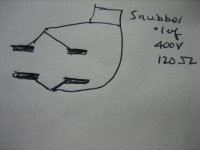
I looked at the power switch and it has four tabs and two on either side are connected together ( ugh?) with the snubber connected across them. Can that be correct? I'll post a pic when I get a chance. In the meantime here is an illustrationAlso check the wiring, it may have been altered during earlier repairs.
Attachments
Last edited:
Power supply to be checked, typical leaks in the diode bridge, and probably the electrolytic capacitors are defective. I would change all that.
I'm not sure what to make of your sketch, but it's disturbing and I believe you're right above the target.
I've attached page 13 from the service manual and it shows the snubber and the details of the power switch. One half of the switch controls AC power to the transformer and the other half interrupts DC power to the speaker relay. The relay should drop instantly with the power switch.
Good luck!
I've attached page 13 from the service manual and it shows the snubber and the details of the power switch. One half of the switch controls AC power to the transformer and the other half interrupts DC power to the speaker relay. The relay should drop instantly with the power switch.
Good luck!
Attachments
There are four tabs on the back of the switch and are externally soldered as shown. The snubber is then connected across. Thanks for the attachment.'m not sure what to make of your sketch
UPDATE: My aging eyes deceived me. Disregard my hand drawn illustration. I removed the underside cover which revealed differently from what I said it was.
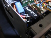
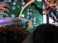
Here are two pics showing the switch with the blue colored snubber. There are only two tabs . The other pic is...well..not what I expect to see, a yellow and a red wire soldered together and just "hanging". I use a pencil to point it out and it would seem from the photo that it is connected to the circuit board but it is not. Seems like this unit was worked on before.
Here are two pics showing the switch with the blue colored snubber. There are only two tabs . The other pic is...well..not what I expect to see, a yellow and a red wire soldered together and just "hanging". I use a pencil to point it out and it would seem from the photo that it is connected to the circuit board but it is not. Seems like this unit was worked on before.
Attachments
Last edited:
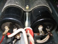
Both Power Supply Caps ( 50V, 10000uf) are also leaky! Any recommendation for replacements?
Attachments
Last edited:
I recommend resolving the relay problem first. One problem at a time...
Hard to tell from the previous pic. Yellow and red wires are soldered to points on the PCB and then joined together out of view above? Are you able to sort out what was done? Symptoms suggest that the DC pole of the power switch has been bypassed. Maybe a continuity check with switch off will reveal what's going on.
Hard to tell from the previous pic. Yellow and red wires are soldered to points on the PCB and then joined together out of view above? Are you able to sort out what was done? Symptoms suggest that the DC pole of the power switch has been bypassed. Maybe a continuity check with switch off will reveal what's going on.

So the yellow and red wires are soldered together and left hanging as pointed out. They are bundled along with other wires and run towards the rear of the amplifier. I cannot at this time say where they terminate. BSST , Thanks for your help thus far.
I believe this switch was changed out. As per schematic what type of switch should this be? Is it possible that the red and yellow wires that are soldered together should have been connected to tabs on the switch? This switch only has two tabs and everywhere that I have looked for the 1070, suggests there should at least be four. In fact , there are switches for the 1070 on Ebay that comes with six tabs and the seller instructs buyers to use the four rearward ones for four wired switches.
You would need a two pole switch, mechanically compatible, and rated for line voltage and current draw from the power transformer. Not a trivial search, but not impossible. I’d start from the Marantz part list—- might offer something useful.
There could be an electrical work-around if you can’t find a suitable switch.
There could be an electrical work-around if you can’t find a suitable switch.
Not sure of compatibility, but I found this:
https://www.awelectronics.com/marantz-2220b-power-switch
https://www.awelectronics.com/marantz-2220b-power-switch
Sounds like you'll have a working amp once you swap out that power switch and correct the botched repair job.
As others have said already: Correct one problem at a time. Resist the temptation to modify. If you absolutely must modify or change components "just because" do so after you get the amp working.
Tom
As others have said already: Correct one problem at a time. Resist the temptation to modify. If you absolutely must modify or change components "just because" do so after you get the amp working.
Tom
Are you sure you are not looking at flux residue?Both Power Supply Caps ( 50V, 10000uf) are also leaky!
If the caps are leaking then you should be able to spot the leaking spot - it does not seem to be visible on the photo.
- Home
- Amplifiers
- Solid State
- Marantz 1070, Loud pop on shutdown