As you are not really making an MTM (the other woofer will be bass only so will not provide the polar response of a true MTM), I would place the woofer above the tweeter (a la Mission) unless you are going to be placing the speaker on high stands and therefore at or above ear level.
This will then angle the sound upwards slightly. Unless you are intending on making a sloping front box and time-aligning that way.
You could get really clever and separate the tweeter and woofer by a quarter wavelength of the crossover frequency and use a 3rd-order Butterworth filter, giving you perfect time alignment with a normal vertical baffle.
Thanks for all the suggestions very interesting.........
Richie boy, i am interested in this sloping baffle arrangement, please explain further, does this utilise three drivers ie tweeter, and two woofers in 2.5 arrangement or a straightforward 2 way.
How complex is the crossover for a flat baffle and are calculators available to assist in the design.
mark
Vikash said:I've got some spare Yamaha 2-way speakers that came with a micro system and was wondering whether the tweeters could be suitable for this project. They are 1" fabric dome, magnetically shielded and look quite nice.
Looks like they would be fine although you will need to measure them yourself for both impedance and frequency.
SimontY said:
Good techincal sense for a sub driver! But wouldn't you be concerned about those frequencies from ~500-100hz or so that are coming from the rear woofer?
Still, it would be really nice from a vibration POV, and maybe those frequencies firing away would add ambience to the sound. Plus - how cool would it be when someone looks round the back to see the port or whatever... and they see a driver!! 😎
Actually this is more a two way with another woofer on the back using the same crossover as the woofer on the front.
Because baffle step works both ways, ie from the front of the cabinet & the rear of the cabinet. When you place a driver on the back the baffle step loss of the rear driver diffracts round the front of the cabinet compensating for the loss of bass from the front driver. This is a similar thing for why dipoles dont suffer baffle step. Ofcourse because the rear driver is producing all the high frequencies too, speaker placement is more critical for the same reasons a dipole placement is more important.
Hmm thats got me thinking, ill do a rear mounted MTM for my pair and see how that turns out.
I thought this may be of interest to others involved with this thread.
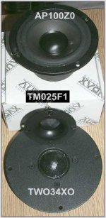
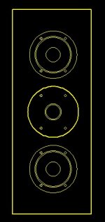
Alot of the designs i am CADing seem to look odd due to the 34mm tweeter, any suggestions on layout. I really am considering using the F1 on this project and saving the 34XO for another.
Alot of the designs i am CADing seem to look odd due to the 34mm tweeter, any suggestions on layout. I really am considering using the F1 on this project and saving the 34XO for another.
Attachments
D1GGY,
For 'normal' flat, vertical baffle:
You can do it as a 2-way or 2.5-way as the 0.5-way part can be considered separately from mid-high crossover. 3rd-order Butterworth with reverse-polarity connected tweeter is the way to do it.
The crossover network is no more complex than any other 3rd-order filter. The clever/tricky part is spacing things out according to the correct wavelength and choosing the appropriate crossover frequency.
The theory is fairly complex to a crossover newbie, but basically the 3rd-order filter has a -15 degree tilt in the polar response due to the phase differences between woofer and tweeter. If you space the tweeter and woofer apart appropriately, i.e. +15 degrees tilt, you can make the combined tilts cancel each other out and so you get a straight-forward directional reponse.
You could work out the required driver spacing with trigonometry, but this is just a theoretical starting point. The radiating point for each driver at the crossover frequency may not be where you think. Complex measurement is the only way to be sure.
I would also do it as TMM configuration, as when the baffle step driver comes in it will be not be as close to the midrange as it could be. EDIT: hmmm, that would make it a bit dodgy doing the upside-down tweeter and mid arrangement then...
Is the baffle step not affected by the out-of-phase dipole vs bipole?5th element said:When you place a driver on the back the baffle step loss of the rear driver diffracts round the front of the cabinet compensating for the loss of bass from the front driver. This is a similar thing for why dipoles dont suffer baffle step. Ofcourse because the rear driver is producing all the high frequencies too, speaker placement is more critical for the same reasons a dipole placement is more important.
Don't forget about internal standing waves. You might want to design around a volume rather than just the baffle dimensions...D1GGY said:my initial thoughts on the front baffle........
19cm wide, 50cm tall.......depth as required for volume.
Vikash said:
Is the baffle step not affected by the out-of-phase dipole vs bipole?
Yes ordinarily this happens in a dipole because the rear wave is being produced by the rear of the cone, there fore the two sound waves being produced fromt he front and the back are out-of-phase.
However in a 2.5way with the .5 thing mounted on the rear of the cabinet, the rear driver moves in the opposite direction in comparison to the rear of the cone in a dipole set up.
So dipole, Front of the cone moves forwards and the rear of the cone also moves the same way towards the front of the cabinet.
In a 2.5 rear mount - the front drivers cone moves fowards towards the listener, but the rear driver fires away towards the back wall producing opposite phase of a dipoles rear wave. Thus the two drivers, on the front and back, sum constructively.
Thats a bit of a mishmash of words so i hope it makes sense.
Vikash,
my text may be little misleading, The dimensions were calculated by winisd, i could not remeber the depth measurement hence my whatever statement. Am i correct in interpreting your comment that i should only use the "optimum" dimiesnions offered by such software?
In Which case my measurements are a little tweaked.
5th element et all....
If i undestand all of this correctly i mount one wooofer in the front baffle, one in the back directly opposite with the port above it on the back panel. Tweeter mounted at the top, any offset or direct in line with the front woofer. does the tweeter need to be mounted away from the edges?
The crosssover will then be a 2.5 design with the .5 part associated with the "rear" woofer
D1GGY said:I really am considering using the F1 on this project and saving the 34XO for another.
I must admit that I've not been following / reading this forum - but please reconsider using the F1...It's really not nice. I used it in an Audax speaker that used to be published on the Audax.com website...I didn't like it at all.
Just my opinion of course...Good luck!
Gaz
Not at all. I don't know what ratio WinISD uses, but there are many irrational ratios to choose from including the golden ratio. You can use this calculator to check if your enclosure has standing waves that clash: http://www.vikash.info/audio/standing_wave_calc/D1GGY said:Am i correct in interpreting your comment that i should only use the "optimum" dimiesnions offered by such software?
Gaz,
interesting you should say that, I did wounder when i opened that packet how it would sound looking at the two the F1 does look rather cheap in comparision to 34 and my other tweeters from other projects
m
interesting you should say that, I did wounder when i opened that packet how it would sound looking at the two the F1 does look rather cheap in comparision to 34 and my other tweeters from other projects
m
vikash thanks i will give it a wiz when i get in.
i am about to start my 1.25 hr trip home catch you all later
m
i am about to start my 1.25 hr trip home catch you all later
m
This tweeter seems to be used in a system called the:
Arcaydis AKS Monitor retailing at £259 / pair.
See Hifi News (June 2002) for a review. I'm sure it's used in many other systems too though.
Gaz
Arcaydis AKS Monitor retailing at £259 / pair.
See Hifi News (June 2002) for a review. I'm sure it's used in many other systems too though.
Gaz
vikash, i used your calculator and got:-
Mode Height Width Depth
1 357 Hz 903 Hz 522 Hz
2 715 Hz 1.81 KHz 1.04 KHz
3 1.07 KHz 2.71 KHz 1.57 KHz
4 1.43 KHz 3.61 KHz 2.09 KHz
5 1.79 KHz 4.51 KHz 2.61 KHz
6 2.14 KHz 5.42 KHz 3.13 KHz
7 2.50 KHz 6.32 KHz 3.65 KHz
8 2.86 KHz 7.22 KHz 4.18 KHz
would you be kind enough to expalin what it all means?
Mark
Hi Mark, I have briefly explained here: http://www.diyaudio.com/forums/showthread.php?postid=356207#post356207
At a quick glance I can't see any clashing numbers, or close sets of numbers which means the standing waves are spread out ok.
Updating that calculator is on my to do list so that it highlights it for you, and possibly even tries some ratios and picks the best one out for a given enclosure volume. But where to find the time...sigh.
sreten said:Just point out to you all the 34mm audax tweeter is as old as
the hills (almost) and dates back to the days of the ubiquitous
1" Audax soft dome in nearly every decent speaker.
There were two versions, this does appear to be the high efficiency.
🙂 sreten.
I've also jumped on the bandwagon - 6 of these AP100Z0's arrived this morning, and they sound quite promising mounted in a cardboard box 😉
I realise this is a bit late in the thread, but I just thought I'd mention that I believe this 34mm tweeter was used in the BBC designed LS5/8 and LS5/9 systems - these designs date back to the late 1970's (there's some stuff about them on my WWW). The price reduction is certainly good news for anyone that wants to hold a couple of spares.
It's been a while since I did any speaker design, and back in those days I calculated everything by hand. I see a variety of CAD packages are in use here - although perhaps off-topic, could anyone provide pointers (to another thread, perhaps) or recommendations towards the best packages?
Also, I was attracted to the F1 driver on aesthetic grounds, but I saw Gaz's comment. Any other recommendations for a small unit that won't look too big next to these tiny woofers?
Thanks for spotting them, PM
Mark 😉
no time like the present...I've updated the calc so it highlights similar standing waves. What were the actual values you used Mark? (might be better to send the URL 😉 )
D1GGY said:5th element et all....
If i undestand all of this correctly i mount one wooofer in the front baffle, one in the back directly opposite with the port above it on the back panel. Tweeter mounted at the top, any offset or direct in line with the front woofer. does the tweeter need to be mounted away from the edges?
The crosssover will then be a 2.5 design with the .5 part associated with the "rear" woofer
No the crossover is designed without ANY bafflestep compensation whatsoever and the second driver is not a .5 driver. You simply design an MTM but without any BS compensation built in.
Mounting the second driver on the rear of the cabinet with the same output as the driver on the front completly compensates for baffle step. If you understand how bafflestep works you will understand how this works. I have several posts where I have described baffle step so do a search and you'll find em.
Dipoles dont suffer bafflestep because bafflestep is compensated for in the same way the driver on the front and back will work. However in a dipole the front and rear wave are out of phase with one another so it creates a roll off of 6dB per octave into the bass. If this is compensated for then you get a flat frequency response.
- Status
- Not open for further replies.
- Home
- Loudspeakers
- Multi-Way
- Maplins close-out on AP100Z0