As well as @Mark Tillotson suggestions I find taking time constants out of the equation helps a lot, well making them so large they become a non issue. The input coupling cap can be '1' and so can the feedback return.
Set the sim to run for say 200ms and start saving at 140ms. You can also usefully alter this to reduce the range of the FFT.

Set the sim to run for say 200ms and start saving at 140ms. You can also usefully alter this to reduce the range of the FFT.

Hi all, thanks for the FFT tips, very useful.
I've been reading the excellent Douglas Self data about amplifiers and the 8 distortions, on his website, and trying a few things. Well, quite a lot of things..
I can only conclude that there's some type of magic going on in this amplifier, perhaps the Wilson stage, as I can't get very close, let alone beat the distortion figures of the original.
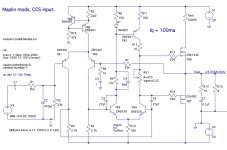
But there is one mod I tried, simply putting a basic CCS on top of the input stage, that seems to have a dramatic effect, so perhaps for my Maplin amp board simply changing the 47k resistor for this might be the only mod.
The current's a bit higher so the bias needed adjusting back to 100mA, but I'm a bit staggered to how good it is.. looking at those harmonics fall away, no hash. Perhaps it's a fluke, but it's a very interesting one 😀
I've been reading the excellent Douglas Self data about amplifiers and the 8 distortions, on his website, and trying a few things. Well, quite a lot of things..
I can only conclude that there's some type of magic going on in this amplifier, perhaps the Wilson stage, as I can't get very close, let alone beat the distortion figures of the original.
But there is one mod I tried, simply putting a basic CCS on top of the input stage, that seems to have a dramatic effect, so perhaps for my Maplin amp board simply changing the 47k resistor for this might be the only mod.
The current's a bit higher so the bias needed adjusting back to 100mA, but I'm a bit staggered to how good it is.. looking at those harmonics fall away, no hash. Perhaps it's a fluke, but it's a very interesting one 😀
Attachments
Hi all, Well, I was a bit suspicious of the super smooth harmonics.. and so it turns out that CCS mod had the major effect of altering the offset and bias just enough to keep it in class A... with the 0.1V input 😀
That's probably why class A sounds so nice!
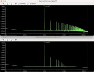
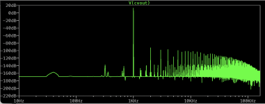
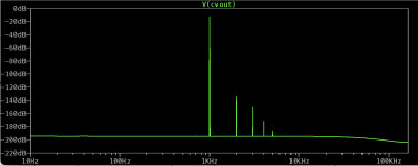
Below are the FFTs of 0.05V and 0.2V, of the same circuit, showing the crossover distortion as it enters class B. This is why my Douglas Self improvements didn't help - all (most of) the distortion was from the crossover....
So that's the next thing to look at.
The 100mA bias is good for stability and gives almost 1 Watt in class A which will sound lovely... but it's probably sub-optimal for crossover distortion.
That's probably why class A sounds so nice!
Below are the FFTs of 0.05V and 0.2V, of the same circuit, showing the crossover distortion as it enters class B. This is why my Douglas Self improvements didn't help - all (most of) the distortion was from the crossover....
So that's the next thing to look at.
The 100mA bias is good for stability and gives almost 1 Watt in class A which will sound lovely... but it's probably sub-optimal for crossover distortion.
Attachments
Hi all!
So I've been experimenting in LTspice some more, and working on a 'minimal modification' set for the Maplin / Hitachi schematic.
This is now what LTspice says:
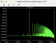
THD
0.01V in (Class A)
Partial Harmonic Distortion: 0.000085%
Total Harmonic Distortion: 0.000000%
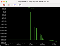
THD
0.2V in (Class AB/B):
Partial Harmonic Distortion: 0.000800%
Total Harmonic Distortion: 0.000602%
And it clips much more gracefully too, which is nice, and the offset is < 1mV, and idle is about 50mA.
So how is this achieved?
Well I read some Douglas Self, and the original Maplin article, and played a lit with some very subtle changes.
The effect of these small changes is to massively increase the open loop gain, via an input CCS and some very subtle balancing of the two LPTs. this makes the GNFB work better. I'm not a fan of GNFB, but with Class B, I see little alternate.
Stability seems Ok, but I had to add a resistor of 270k to prevent a latchup condition, where the final Wilson current source+mirror left the gates dangling, TR5 completely off, so it got locked into a -50Vdc thing, probably not ideal...
BTW I tested on 50V mainly but on 60V just now, so the rail voltage is at 60V in the schematic.
So why does the distortion fall? Well, most is due to the horrible crossover distortion, so the GNFB is really racing about to tame this. These artifacts are seen in the 2nd FFT, and suggest MOSFETs are best in Class A 🙂
So my mods can really be categorised as 'making the GNFB work better with hints from Douglas's webpage).
I chose 0.2V input for most testing as it's just into the crossover region where MOSFETs switch off, but at listening levels (6Vish) that are common - and where the crossover distortion would be a problem.
So now, unless there are terrible errors about to leap out in the hardware (ringing, latchup, dodgy HF etc), I'll mod my 2 boards to this spec and see what it does.. after cleaning the dust from the soldering iron 😀
So I've been experimenting in LTspice some more, and working on a 'minimal modification' set for the Maplin / Hitachi schematic.
This is now what LTspice says:
THD
0.01V in (Class A)
Partial Harmonic Distortion: 0.000085%
Total Harmonic Distortion: 0.000000%
THD
0.2V in (Class AB/B):
Partial Harmonic Distortion: 0.000800%
Total Harmonic Distortion: 0.000602%
And it clips much more gracefully too, which is nice, and the offset is < 1mV, and idle is about 50mA.
So how is this achieved?
Well I read some Douglas Self, and the original Maplin article, and played a lit with some very subtle changes.
The effect of these small changes is to massively increase the open loop gain, via an input CCS and some very subtle balancing of the two LPTs. this makes the GNFB work better. I'm not a fan of GNFB, but with Class B, I see little alternate.
Stability seems Ok, but I had to add a resistor of 270k to prevent a latchup condition, where the final Wilson current source+mirror left the gates dangling, TR5 completely off, so it got locked into a -50Vdc thing, probably not ideal...
BTW I tested on 50V mainly but on 60V just now, so the rail voltage is at 60V in the schematic.
So why does the distortion fall? Well, most is due to the horrible crossover distortion, so the GNFB is really racing about to tame this. These artifacts are seen in the 2nd FFT, and suggest MOSFETs are best in Class A 🙂
So my mods can really be categorised as 'making the GNFB work better with hints from Douglas's webpage).
I chose 0.2V input for most testing as it's just into the crossover region where MOSFETs switch off, but at listening levels (6Vish) that are common - and where the crossover distortion would be a problem.
So now, unless there are terrible errors about to leap out in the hardware (ringing, latchup, dodgy HF etc), I'll mod my 2 boards to this spec and see what it does.. after cleaning the dust from the soldering iron 😀
Attachments
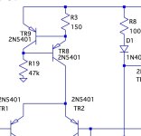
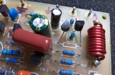
Some updates, soldering up the mods, the R3 47k resistor is swapped out for the CCS.
Of course it may all go horribly wrong, but I have a Variac, this thing simulates OK on +/- 9V rails so hopefully I can test it without any magic smoke 😀
The input cap is now a 10uF, bypassed on the back, the 220u NFB one is bypassed by the ridiculously large 820n that was spare), the new pots are in, with red LEDs across (safety if RV1 goes open circuit) and a 220n, R9 on one of the (long suffering) PCBs is a bit small, but has survived so far and I don't seem to have a bigger 12k spare to replace it.
C4 was re-drilled on end to be the 270k 'bleed' - this is R17 on my mod schematic as I found it necessary to have a tiny bit of current to pull the gates up, when the wilson current mirror at the top was fully engaged (TR5 fully off)
R4, R5 and R10 are changed out to 1.5k, 1.5k, 150R, I'm waiting for some 1kv 33pF caps for C5 and C6.
I also found some neat inline 20mm fuse holders, so I got 4 with 2AT fuses, to go on the power rails after the big caps, just as a sensible thing and it matches the original schematic, so I'll work those in too.
I'm interested to see it it all actually works, we'll see 🙂
Attachments

Hello all
test rig completed and sounds fantastic .. even my HiFi friends are surprised as they are young chaps who have never heard of DIY audio make stuff your self and sounds better then their current equipment

test rig completed and sounds fantastic .. even my HiFi friends are surprised as they are young chaps who have never heard of DIY audio make stuff your self and sounds better then their current equipment
This does pack a punch .. honestly our family think this would cost thousands

these Mosfet' s where removed from a skip as salvage ... now they are singing again in this build
just love recycling stuff that people have no idea what they are disposing of .... 😉
just love recycling stuff that people have no idea what they are disposing of .... 😉
I'm so on board with this, the two PCBs I'm modding are also scrap found, arriving at differing times via my brother when he scouted council tips for a cycling charity for abandoned cycles.these Mosfet' s where removed from a skip as salvage ... now they are singing again in this build
just love recycling stuff that people have no idea what they are disposing of
It's a bit heartbreaking knowing what some stuff is that's discarded, but equally cheering when things can be saved 🙂
I'm also of the era that grew up seeing these things new, shiny and sought after! We've gone backwards in significant ways, starting in 1764 in a way, but the last great 'hurrah' of this era was I think, for me, between the 1950s and 2010.
hello stv
yes I spent some time with this .. as My board is a new design I added extra copper space for tab terminals
so yes .. I am pleased with the overall result
yes I spent some time with this .. as My board is a new design I added extra copper space for tab terminals
so yes .. I am pleased with the overall result
- Home
- Amplifiers
- Solid State
- Maplin MosFET Amplifier GA28F construction thread